Sony KLV-48W652D Main Board Voltage Chart | Full Testing Guide
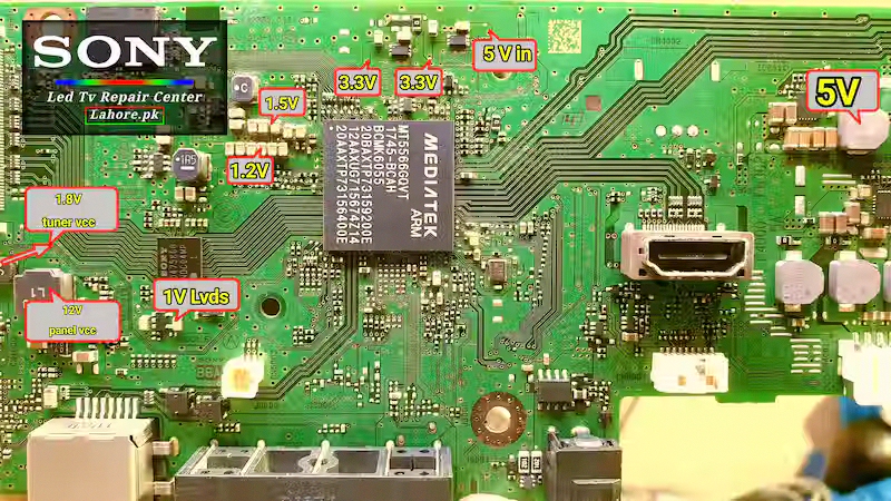
Sony KLV-48W652D Main Board Voltage Chart Our article is about the voltage details of this model of mainboard. Earlier, we shared the fault of the same model in Dead Fault. If you want to read that article, click here. In this article, we will discuss the voltage details of this Sony model in detail, what voltage is for what, and what effects it has on the system if that voltage is missing. This article is purely a technical article, and I will include as much technical detail as possible about this board so that fellow technicians can benefit from it. We will include an image in which all the voltages are annotated, indicating where each voltage will come from, and we will explain all the voltages in detail in this article. I hope this article will help the technician.
Voltage Overview of KLV-48W652D Main Board
So let’s first see how many voltages there are in this main board. We see this in this board, respectively. There is a 19-volt main power supply followed by a 5-volt power supply followed by two regulators that generate 3.3 volts. The core voltages for its system are 1.5 and 1.2 volts, while 1.8 volts is used for the tuner contains a regulator that takes an input of 19 volts and generates 12 volts, which is the VCC supply for our panel. It has another one-volt power supply that is used for the LVDS IC. This is the voltage detail of this motherboard. Now we will discuss its sequence, and moving forward, we will discuss the role that voltage plays. Step by step we will understand these voltages in the lines below. So that my technician friends can better understand the theory of this board.

Power Rail
- 19 Volt Main Power Supply This power supply goes directly to the five-volt regulator.
- This 5-volt power supply has two regulators of 3.3 volts, which go straight to them.
- The 5-volt power supply once again goes straight to the 1.5-volt regulator, which in turn supplies the system IC.
- The voltage is taken from the five-volt regulator and given to the 1.2-volt regulator, and this 1.2-volt goes directly to the system.
- The input of the 1.8-volt supply for the tuner is from the five volts, and this 1.8 voltage is used for the tuner section.
- The panel VCC power supply is supplied from 19 volts for 12 volts, which is fed to this regulator, and it generates 12 volts for the panel.
- There is a one-volt power supply for LVDS signal processing, and the input of this power supply is fed by a 1.5-volt regulator.
Voltage Summary
I have tried my best to accurately describe the voltage details of this Sony model and honestly share my knowledge with you. We have explained the voltage trail step by step in this, which voltages come from where and where they go, and my purpose in writing this is to make it easy for the technician.
Conclusion
In this article, we have provided details of all the voltages used in this Sony model. Because without voltage details, you cannot repair any LED television board; unless you have exact voltage details, you cannot do fault finding. We have calibrated all the voltages of this board step by step in full detail and have also given you their trails as to where those voltages come from and how they are generated. We have written all this in this article. I hope this article will be very helpful for my fellow technicians, and people will benefit from it. Please also comment on what kind of fault finding you need.
FAQs–Voltage Testing in Dead Sony LED TV
Q1 In a dead condition, you first have to check 19 volts, then five volts, then 3.3 volts. If any of these voltages are missing, you should check the regulator circuit, check its IC, check the input voltage, and check its feedback to the IC.
Q2 If the voltages given above are correct, then you have to check its 1.5 voltage and 1.2 voltage. There will definitely be some voltage missing from them, and their method is also the same: you check their input supply and check their feedback to the IC.
