
V400HJ6-PE1 C2 Panel Test Point COF DATA
In this article, 5276-ACBR6 COF DATA with V400HJ6-PE1 C2 panel is explained in detail, where you will get complete COF DATA reference along with practical understanding of the panel structure. This content provides Chip on film reference data in a clear way so that the technician can easily relate it with real board-level testing. Along with this, you will also discover COF data and COF datasheet style reference points, including panel test point details for accurate fault analysis. The article is supported with images showing both COF reference layout and panel test point identification for better understanding.
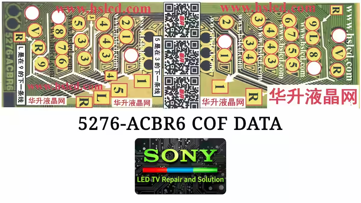
5276-ACBR6 COF Test Points
The image below shows the complete COF DATA test point details for this specific chip. Here you can clearly identify all relevant measurement points related to this COF section, which help in accurate troubleshooting and panel-level diagnosis. These test points are useful for checking voltage levels, signal paths, and continuity during fault finding, making it easier to understand the actual working condition of the panel.
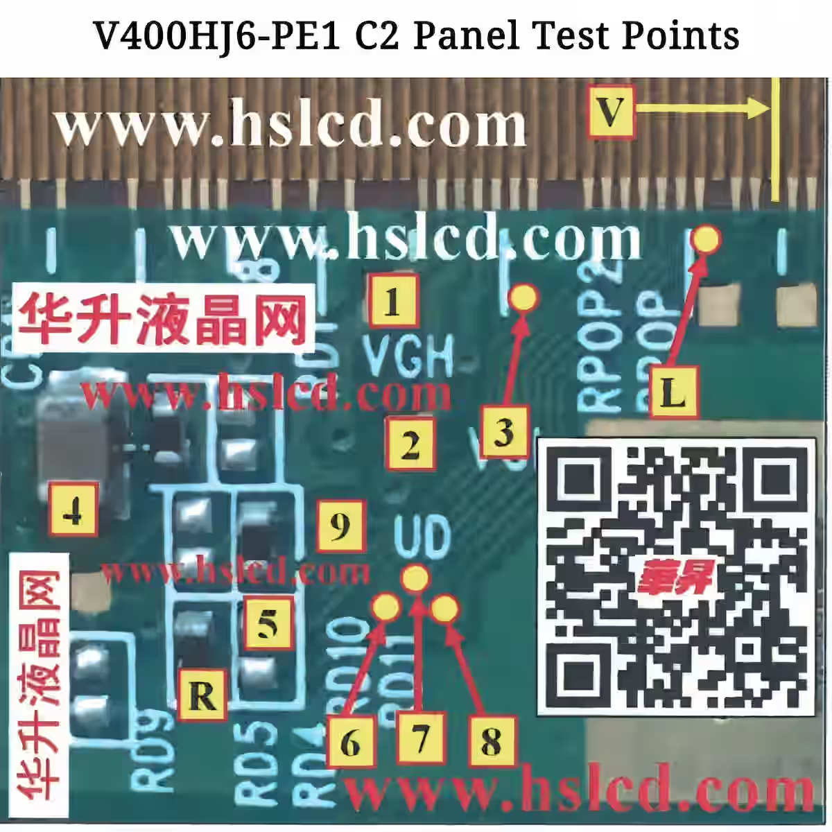
V400HJ6-PE1 C2 Panel Test Points
In the image below, you can clearly see all the test points related to the side COF of the V400HJ6-PE1 C2 panel. These points help in understanding the actual signal and voltage paths inside the panel and are very important for accurate fault diagnosis. With this reference, you can easily identify each test point location and understand its role in the panel operation.
COF Role in Panel Operation
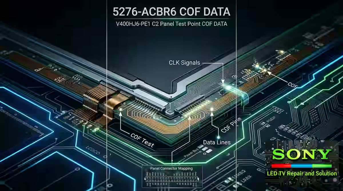
In a side of panel structure, the COF plays a critical role in overall signal distribution and voltage handling across the display. It is responsible for carrying the driving signals from the main processing section into the panel lines in a controlled manner, ensuring stable communication between the T-CON side and the LCD matrix. In terms of voltage distribution, it helps maintain proper levels required for gate and source lines so the panel operates without flickering or distortion.
Another important function is pixel control. The COF works as a bridge that delivers precise timing signals needed to activate and control individual pixels, which directly affects image clarity and uniformity. If any fault occurs in this section, it can lead to issues like line defects, half display, or complete panel failure. That is why understanding this COF section is essential for accurate panel-level diagnosis and repair.
Conclusion
In conclusion, 5276-ACBR6 COF DATA with V400HJ6-PE1 C2 panel provides a complete reference for understanding the COF section in a practical repair environment. This guide helps in identifying key signal paths, voltage distribution, and panel behavior through proper Chip on film reference data. By using the provided COF test points and panel test point details, a technician can perform accurate fault diagnosis at board level.
The information shared in this article, including COF datasheet style references and structured panel analysis, makes it easier to discover COF data in a real troubleshooting scenario. With proper understanding of these points, issues related to display lines, signal loss, or panel malfunction can be traced more efficiently, leading to better and faster repair decisions. All the visual reference data and images included in this article further support the explanation, making it easier to identify each COF section and its corresponding test points directly from the panel layout.

Shaukat Ali has over 30 years of experience in LED TV repair, specializing in chip-level repair work. He is an expert in Sony LED TVs, and also repairs other major brands like Samsung, TCL, Orient, and Haier. His expertise includes display panel faults, motherboard issues, power supply circuits, T-Con, and HDMI faults. Based in Lahore, he shares real-time fault finding cases from daily repair work to help technicians and learners with practical experience.
📞 Contact: +92 321 4066054