
LD Board Backlight Fault Diagnosis
When working on the KDL-40W600B 6 Blink Error Fix, the set was showing an irregular behavior during operation. In some cases, the TV would run completely normal without any issue, but after some time it suddenly shifted into 6 blink error protection mode, and the system went into protection.
This kind of fault is not constant, which makes it more tricky during initial checking. The TV could stay ON for a while, but randomly the protection circuit would trigger and the unit would shut down with 6 blink error indication. This behavior clearly pointed towards an unstable condition in the LD board backlight fault section, which needed proper step-by-step diagnosis.

KDL-40W600B 6 Blink Error Fault Analysis
When moving forward with the KDL-40W600B 6 Blink Error Fault Analysis, the first step was to open the set and carefully inspect the overall condition. Since this fault is commonly related to backlight failure, 6 blink error is usually generated when the backlight section or protection circuit is triggered. However, in some cases it can also be linked with circuit level issues, so proper checking is always required.
To confirm the fault area, I first checked the backlight separately by isolating it from the main system, and it was found to be working fine. After confirming that the backlight was OK, the focus was shifted towards the circuit side, and the LD board was examined in detail. During this inspection, a fault was identified on the LED driver IC section where a resistor connected to pin number 34 was found damaged. This point will be explained in detail in the next section, where we will analyze the exact role of this component in the circuit.
LD Board Driver Circuit Diagnosis
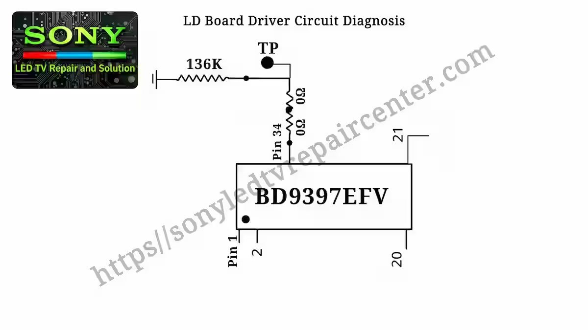
In the LD Board Driver Circuit Diagnosis section, the main LED driver IC used in this board is BD9397EFV, which controls the backlight driving and protection functions in the circuit. In this specific KDL-40W600B model, the fault was traced around pin number 34 (RT pin) of this IC. This pin is used for the DC-to-DC frequency setting resistor, where a resistor is connected between the RT terminal and ground to control the operating frequency of the driver circuit.
This IC is also used in different Sony models, but the resistance value connected to the RT pin can vary from model to model depending on the circuit design and backlight requirement. In this particular case, the resistor connected to the RT pin was found faulty, which was disturbing the LD board operation and causing the TV to enter 6 blink error protection mode intermittently.
For better understanding, we are also providing the circuit reference image below where the RT pin section and its related resistor network can be seen clearly in a simplified block diagram style.
KDL-40W600B 6 Blink Fault Repair Solution
In the KDL-40W600B 6 Blink Fault Repair Solution, the fault was traced around the RT section of the BD9397EFV LED driver IC. On pin number 34, this model uses a resistor network where three resistor positions are available in series configuration. In this specific board design, the first four positions on the ground side were used as jumpers, while the main resistor connected with pin 34 was a 136K resistor.
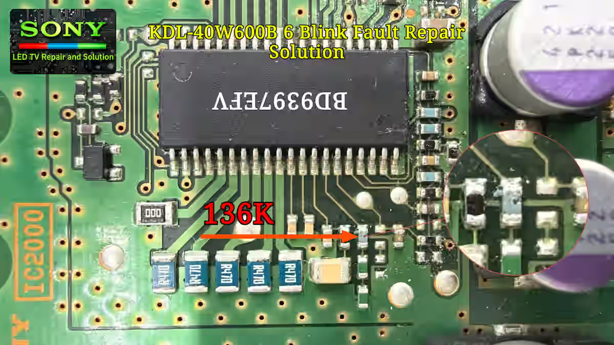
In many other Sony models, this resistance value is divided into multiple resistors, but in the KDL-40W600B model Sony used a single 136K resistor in this section. During inspection, the resistor was visibly damaged and its burned condition could also be observed physically. You can clearly see this affected component in the image below where the faulty resistor area is highlighted for reference.
After replacing the damaged 136K resistor, the LD board was assembled back into the set and the TV was placed under continuous testing. During testing, the protection issue did not return and the 6 blink error fault was completely resolved. After proper verification and stable operation, the repair was confirmed as a successful board-level tested fix.
KDL-40W600B LD Board Overview
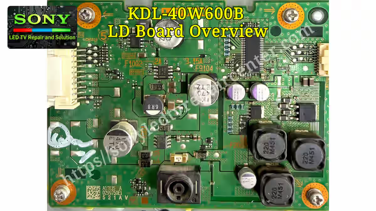
In the image below, we are providing a complete view of the LD board used in the KDL-40W600B model. This section is included to give a clear understanding of the board layout, component placement, and overall circuit design used in the backlight driver system. It helps in identifying how the LD board is integrated with the main system during 6 blink error fault analysis and repair work.
KDL-40W600B Main Board Layout
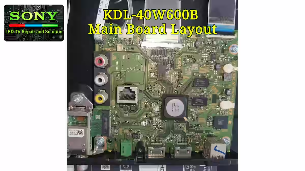
In the image below, you can see the complete main board layout of the KDL-40W600B model used in this Sony LED TV. This board contains the major control sections of the set, including the signal processing area, power communication lines, protection circuit section, and the interface connections linked with the LD board and backlight control system.
This reference image is being included to give technicians a clearer understanding of the overall board structure and component arrangement used in this chassis design. It can also help during board-level diagnosis, circuit tracing, and protection fault analysis when working on issues related to 6 blink error, unstable operation, or backlight protection conditions in the KDL-40W600B series.
- The TV was operating normally at times, but randomly shifted into 6 blink error protection mode during operation
- Initial testing confirmed that the backlight itself was working properly, which shifted the diagnosis towards the LD board driver circuit
- Detailed board-level checking identified a faulty resistor connected with pin 34 (RT pin) of the BD9397EFV LED driver IC
- The damaged 136K resistor was replaced, the LD board was reassembled, and continuous testing confirmed that the 6 blink error fault was completely fixed
Conclusion
The KDL-40W600B 6 Blink Error Fix discussed in this article was related to the LD board driver circuit, where an unstable resistor connected with the BD9397EFV LED driver IC was causing the TV to enter protection mode intermittently. Because the fault was not constant, proper testing and step-by-step diagnosis were necessary to separate the backlight section from the circuit fault and accurately locate the defective component.
After detailed board-level diagnosis, the damaged 136K resistor connected with pin 34 (RT pin) was replaced and the LD board was tested carefully under continuous operation. Once the faulty component was repaired, the protection issue disappeared completely and the TV started working normally again. This repair case also shows how important proper circuit analysis and practical fault finding experience are when dealing with Sony 6 blink error protection faults.
Related Blink Error Articles
If you want to explore more Sony 6 blink error fault finding articles, additional repair cases and board-level diagnosis guides are available below. These related articles cover different Sony models, protection faults, backlight issues, and tested repair solutions to help technicians understand similar fault conditions more effectively.
Fix Sony KLV-48R472B 6 Blink Error Circuit Issue – Read More
Sony KLV-40R352B Blink Error Circuit Issue – Read More
KD-49XF8000 3 Blink Error Repair Guide – Read More
YouTube Channel
Facebook Page
Pinterest Profile

Shaukat Ali has over 30 years of experience in LED TV repair, specializing in chip-level repair work. He is an expert in Sony LED TVs, and also repairs other major brands like Samsung, TCL, Orient, and Haier. His expertise includes display panel faults, motherboard issues, power supply circuits, T-Con, and HDMI faults. Based in Lahore, he shares real-time fault finding cases from daily repair work to help technicians and learners with practical experience.
📞 Contact: +92 321 4066054