
KD-49XF8000 DC Detection Error & Audio Error
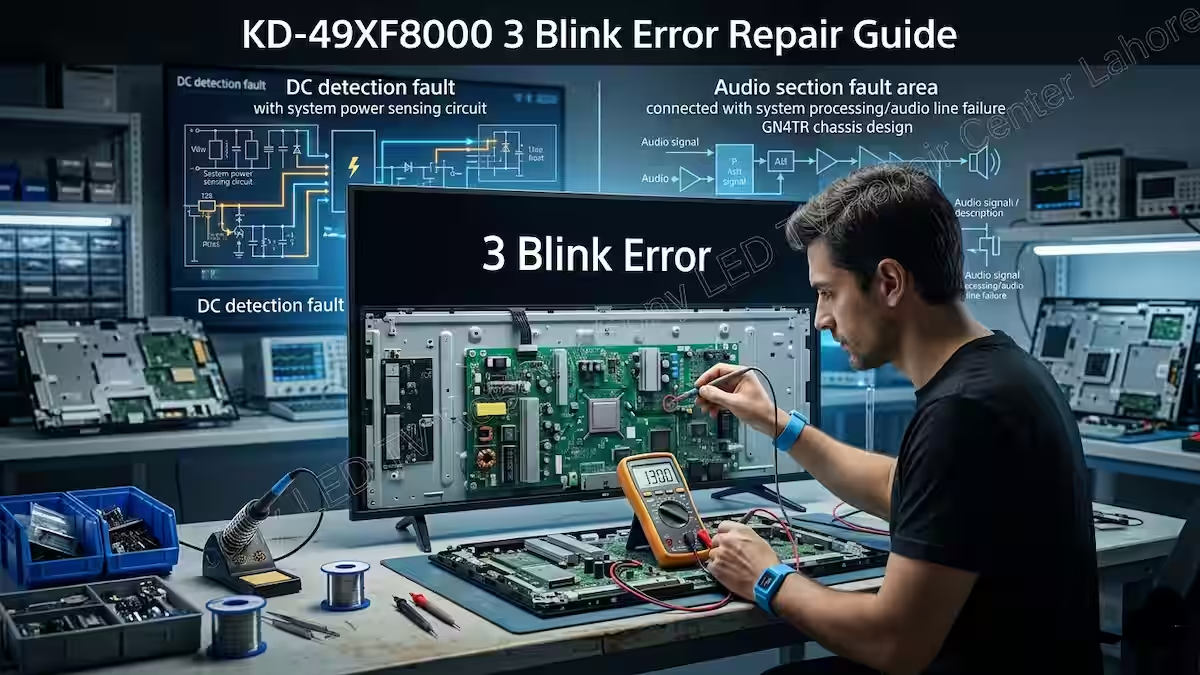
When this fault appears in the KD-49XF8000 3 Blink Error Repair Guide, it is usually linked to two main sections that need careful checking. In this article, we will first explain the 5V DC failure (DC detection circuit) and how this fault is generated and detected by the system IC. Along with this, we will also cover the audio amplifier protection error, because a fault in the audio section can also trigger the 3 blink condition. By understanding both areas step by step, a technician can easily identify the exact fault section.
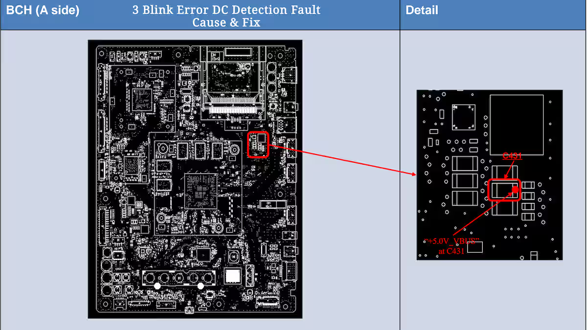
3 Blink Error DC Detection Fault Cause & Fix
In the 3 Blink Error DC Detection Fault Cause & Fix, the first step is to check the +5.0V_VBUS line on the B-Board. This voltage can be measured directly at C431, and it must remain within the proper range of 4.959V to 5.285V. If this voltage is missing, low, or unstable, the system IC detects it as a DC detection fault and immediately triggers the 3 blink protection.
If the 5V line is not within the specified range, the fault may be related to components such as IC402 on the BCH Board, which are responsible for maintaining this voltage line. In some cases, the issue can also shift toward the audio error condition if the system fails to confirm a stable supply. For accurate troubleshooting, refer to the image below where all test points, voltage ranges, and board locations are clearly marked for easy checking.
My Experience with 3 Blink Audio Fault
In my experience with this fault, the first thing a technician should do is properly trace the 5V line and confirm that the voltage is stable and accurate. If the 5V supply is present and still the fault is not resolved, then the next step is to look for the reference path of this 5V near the system IC. This reference is usually created through two or three voltage divider resistors, which provide a feedback signal to the system IC for DC detection.
A practical way to find this point is to use a multimeter in continuity mode on the 5V line and trace it toward the system IC area. There you will find small resistors where this voltage is being divided. If any one of these resistors is faulty or open, the system IC will not receive the correct reference voltage, and it will assume a DC fault condition, resulting in the 3 blink error. This is a deeper level fault, but with proper tracing, it can be identified accurately.
3 Blink Error Audio Amplifier Fault Fix
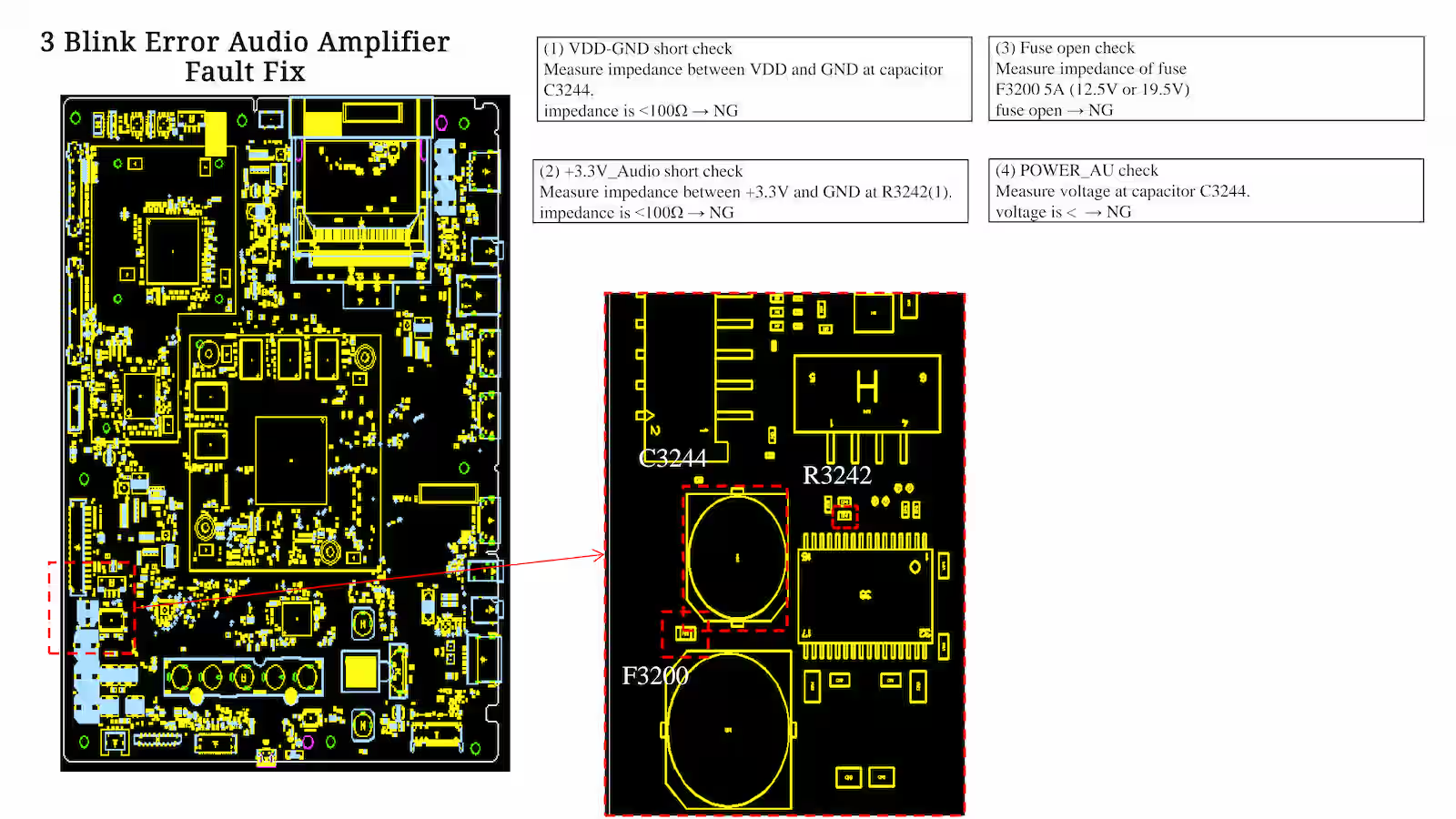
In the 3 Blink Error Audio Amplifier Fault Fix, the fault can start from the basic audio output path, so the first step is to check the speaker harness and speaker condition. Measure the speaker impedance using a multimeter, and it should not be less than 3Ω. If the impedance is low or short, the system will trigger audio protection and shift the TV into 3 blink mode.
Next, move to the BCH-PWB (audio board section) and check for possible faults such as VDD to GND short, +3.3V_Audio line short, or a damaged fuse. Also verify the POWER_AU (VDD) line, which should be supplied momentarily during power-on before the TV goes into protection. If this voltage is missing or unstable, the fault may be related to the G-PWB, LD2-PWB, or AC adapter section. For accurate diagnosis, refer to the image below where all test points, voltage checks, and fault paths are clearly shown for step-by-step troubleshooting.
My Experience with 3 Blink Audio Detection
If a 3 blink error is related to the audio amplifier section, the first step is always to check the main power supply of the audio amplifier IC. In many cases, the IC is not getting proper voltage, which causes the system to detect a fault. Once you confirm that the supply voltage is stable and reaching the IC correctly, then the next step is to move toward the signal path and basic communication lines.
After that, check the source points that carry audio signals from the system IC to the audio amplifier IC. Carefully inspect the small SMD resistors placed in between, because even a slight open or value change can break the communication. Also verify the clock data and control signals step by step. The detect fault pin should be checked as well to ensure it is properly sending feedback to the system IC. In the surrounding area of the IC, if any SMD component looks weak or damaged, it should be replaced to avoid repeat faults.
Conclusion
In the KD-49XF8000 3 Blink Error Repair Guide, the main point is clear that this fault is not caused by a single section. It can come from either the DC detection circuit or the audio protection system. When a technician follows a proper step-by-step approach, checking the 5V DC line, feedback resistors, clock data, and audio amplifier supply, the actual faulty area becomes much easier to locate. In most cases, the issue is linked with weak SMD components or unstable reference signals that push the system IC into protection mode.
For this model, the correct troubleshooting method is to avoid guessing and focus only on real measurements and signal tracing. According to the KD-49XF8000 3 Blink Error Repair Guide, if all voltage rails are stable, communication lines are correct, and the audio section is working properly, the TV will start normally. This structured approach not only helps in quick fault detection but also reduces the chance of repeat failure in the future.
Related Article
If you are working on the KD-49XF8000 series and want to understand the complete fault pattern, then the 2 blink error article is also very important to read. In that guide, I have explained the DC detection and early stage protection faults in detail, which directly helps in understanding how the system IC reacts before shifting into 3 blink condition. For a better flow of troubleshooting, you can check the KD-49XF8000 2 Blink Error Repair Guide through the link given below.
KD-49XF8000 2 Blink Error Fix Guide – Read More
Sony Bravia LVDS 1V Voltage Guide
Sony KDL-40W600B No Power Fault Guide

Shaukat Ali has over 30 years of experience in LED TV repair, specializing in chip-level repair work. He is an expert in Sony LED TVs, and also repairs other major brands like Samsung, TCL, Orient, and Haier. His expertise includes display panel faults, motherboard issues, power supply circuits, T-Con, and HDMI faults. Based in Lahore, he shares real-time fault finding cases from daily repair work to help technicians and learners with practical experience.
📞 Contact: +92 321 4066054