
Step Down Regulator for 12V Panel VCC TPS54332 IC
This article is the next part of our Sony Bravia LED TV repair series, where we have already covered three to four detailed repair guides. In this section, we are focusing on the 12V panel VCC line, which plays a key role in powering the display section from the main board. The TPS54332 step-down regulator controls this voltage line, and in many fault cases, this IC becomes a prime suspect.
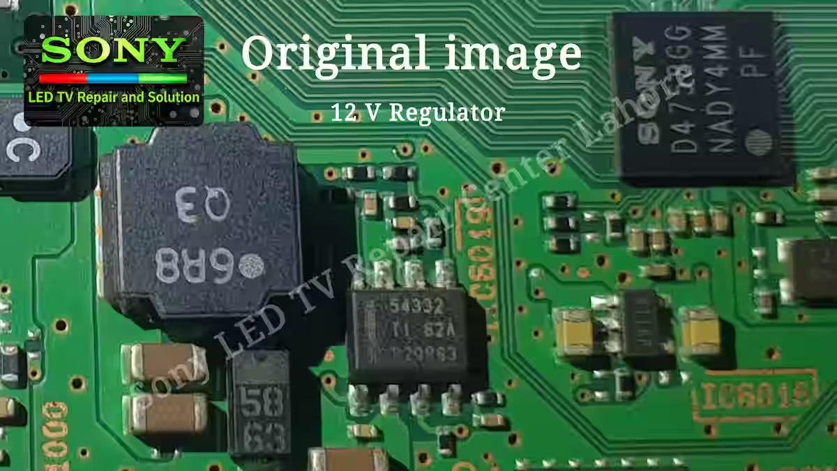
The main purpose of this guide is to help new technicians and beginners understand how voltage lines work on the main board and what points should be checked when there is an issue in the 12V VCC line. We will look at this from a practical repair perspective so technicians in the field can easily trace and diagnose the fault.
TPS54332 IC Overview and Function
TPS54332 is an 8-pin step-down (buck) converter IC used in Sony LED TV main boards, and in this series we are specifically referencing the Sony KLV-40W652D model as a practical example. In this Sony Bravia board, it is commonly used in the power section to generate a regulated 12V output from an input supply of around 19V for panel and logic circuits.
Its main job is to convert higher input voltage into a stable lower output voltage, typically used for panel VCC lines like the 12V rail. This IC is designed for efficient power conversion, so it runs with less heat and provides better stability compared to linear regulators. In the next section, we will go deeper into its current rating, pin configuration, and practical working behavior on the board.
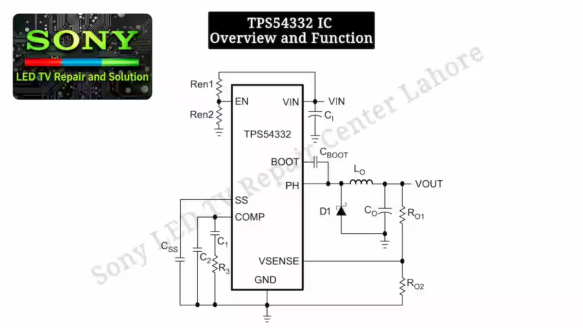
- Pin 1 (BOOT)This is the bootstrap pin used to drive the high-side switch inside the IC. A capacitor is normally connected to this pin, which helps boost the gate voltage during switching operation. If there is any fault on this pin, the IC may not turn on properly and the output voltage can become unstable or completely missing.
- Pin 2 (VIN)This is the main input supply pin of the IC. In Sony Bravia boards, it usually receives around 19V DC from the power section. This voltage is required for the internal switching circuit to operate properly. If the input voltage is missing or unstable on this pin, the IC will not generate the required 12V output.
- Pin 3 (EN)This is the enable pin of the IC. When this pin receives a proper high signal, the regulator turns on and starts switching operation. If the enable signal is low or missing, the IC remains in shutdown mode and no output voltage is produced.
- Pin 5 (VSENSE)This is the feedback sensing pin of the IC. It continuously monitors the output voltage and sends feedback to the internal control circuit. Based on this feedback, the IC adjusts switching to maintain a stable regulated 12V output. If this pin signal is incorrect or disturbed, the output voltage can become too high, too low, or completely unstable.
- Pin 6 (COMP)This is the compensation pin of the IC. It is used for loop stability and control response of the regulator. External resistor and capacitor network connected to this pin helps stabilize the feedback loop and prevent oscillation. If this pin circuit is disturbed or components are faulty, the output may show instability, noise, or voltage fluctuation.
- Pin 7 (GND)This is the ground pin of the IC and acts as the main reference point for all internal operations. All voltages and signals inside the IC are measured with respect to this ground. If there is a poor ground connection or any break in the ground path, the IC may behave abnormally or fail to start properly.
- Pin 8 (PH)This is the switching output (phase) pin of the IC. It is connected to the internal power MOSFET and produces the high-frequency switching waveform that drives the inductor stage. This pin is responsible for transferring energy to the output section and generating the regulated voltage. If there is any fault on this pin or associated components like the inductor or diode path, the output voltage will not be generated properly or may become unstable.
Common Faults TPS54332 IC Sony KLV-40W652D
The TPS54332 IC in the Sony KLV-40W652D main board receives a 19V input and steps it down to generate a stable 12V output for the panel VCC supply. This section is very critical for the display operation, and even a small fault can push the TV into protection mode or standby state. If you need the detailed circuit diagram or a practical repair reference of this IC, you can click here:
In most repair cases, it is commonly observed that the voltage divider resistors in the feedback section drift in value or become unstable, which causes the 12V output to fluctuate. When the feedback signal gets disturbed, the IC receives an incorrect reference voltage, and as a result, the system either goes into protection mode (4-blink error) or fails to start properly.
If the TPS54332 IC in the Sony Bravia 12V Panel VCC Fault Guide (Sony KLV-40W652D) does not generate the required 12V output or the output remains unstable, the TV can also show the same fault condition and enter blink error mode. Therefore, it is very important to carefully check the feedback line, voltage divider resistors, and output filtering components during troubleshooting.
Conclusion
In the Sony Bravia 12V Panel VCC Fault Guide, the TPS54332 step-down IC plays a very important role in generating a stable 12V supply for the panel section in the Sony KLV-40W652D. A proper understanding of its working, input-output behavior, and feedback control makes troubleshooting much easier in real repair situations.
Most of the time, faults are not only inside the IC but also in surrounding components like feedback resistors, compensation network, or output filtering parts. If these points are checked carefully and in a proper sequence, the issue can be traced without unnecessary replacement of the IC. This approach helps in faster diagnosis and more accurate repair results in the field.
Related Articles
If you want to read more of our fault finding repair guides and detailed troubleshooting articles, you can explore the links given below. These articles are part of our Sony Bravia repair series and help you understand different sections and common issues in a practical way.
Sony Bravia 1.8V Power Supply Fault Guide–Read More
TPS54332 Circuit Diagram & Pinout–Read More
KD-49XF8000 2 Blink Error Fix Guide

Shaukat Ali has over 30 years of experience in LED TV repair, specializing in chip-level repair work. He is an expert in Sony LED TVs, and also repairs other major brands like Samsung, TCL, Orient, and Haier. His expertise includes display panel faults, motherboard issues, power supply circuits, T-Con, and HDMI faults. Based in Lahore, he shares real-time fault finding cases from daily repair work to help technicians and learners with practical experience.
📞 Contact: +92 321 4066054