
KD-49XF8000 2 Blink Error Complete Solution
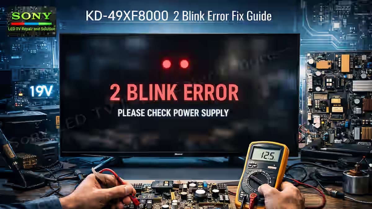
The Sony KD-49XF8000 2 Blink Error Fix Guide is focused on a common power supply fault where the issue is usually in the main 12V line. In this model, the fault is related to the 12V line, so jumping to a direct conclusion is not the right approach. The Sony KD-49XF8000 comes in two different versions — one with an external adapter and the other with a built-in power supply. In this guide, both versions will be covered separately with a proper step-by-step method to trace the fault.
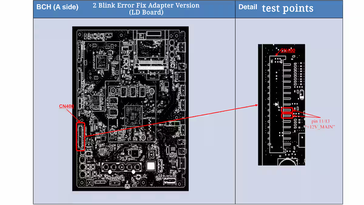
2 Blink Error Fix Adapter Version (LD Board)
In the LD board version of Sony KD-49XF8000 2 Blink Error Fix Guide, the fault tracing starts from the input side where 19V is received on the LD board. Inside this board, a step-down regulator converts this supply into the main 12V line, which is then sent to the main B-board for further processing.
To confirm the fault, check the +12V_MAIN voltage at CN400 connector pin 11 and pin 13 on the B-board. If the voltage is above 13.2V, the circuit is considered normal and the fault should be traced further towards the BCH board side. If the voltage is not present or low, the issue is most likely in the LD board section, where the 12V generation circuit or regulation stage may be faulty.
This method clearly separates the power generation stage and the distribution stage, making it easier to isolate whether the 2 blink error is coming from the LD board or the downstream sections. In the image below, all these test points including CN400 pin 11/13 and the +12V_MAIN measurement point are clearly shown for better understanding and practical fault tracing.
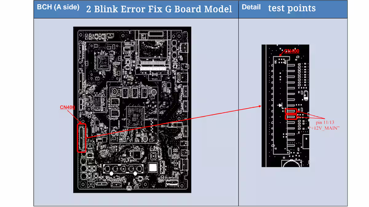
2 Blink Error Fix G Board Model
In the G Board version of Sony KD-49XF8000 2 Blink Error Fix Guide, the fault tracing starts from the main power board section where all the required supply voltages are generated directly. This board is responsible for producing stable output rails that are distributed to the rest of the system for proper operation.
To confirm the fault, check the +12V_MAIN voltage at CN400 connector pin 11 and pin 13 on the B-board. In this version, the main power board generates the required supply, and this voltage is sent towards the main circuit for system operation. If the voltage is above 13.2V, the power stage is considered normal and the fault should be checked further on the BCH board side.
This clearly shows that in the G Board model, diagnosis is focused on the main power generation stage, where the key voltages are produced and monitored for 2 blink error troubleshooting. In the image below, all these test points including CN400 pin 11/13 and +12V_MAIN measurement point are shown for practical checking and better understanding.
2 Blink Error System IC 1.2V Reference Point
In Sony TVs, the system IC continuously monitors the main supply line to confirm that the power stage is working correctly. The IC does not directly work on 12V; instead, it senses this voltage through a resistor voltage divider network, which steps down the 12V into a lower reference level, usually around 1.2V, for safe monitoring inside the processor.
This divided voltage is then used by the system IC as a reference signal. If this reference level is stable and within range, the IC considers the power supply healthy and allows normal startup without triggering a 2 blink error. But if this sensed voltage is missing or unstable, the system detects a fault in the power section and immediately generates a protection response.
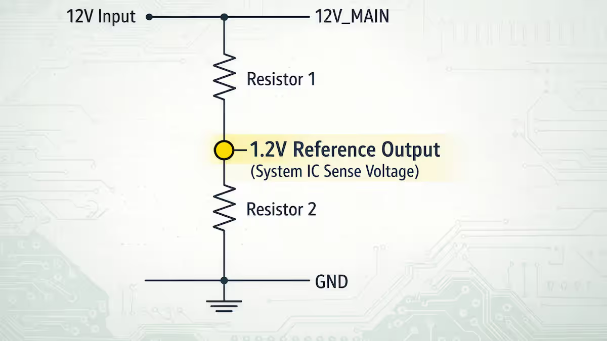
For deep fault finding, this reference sensing point becomes very important, because it helps identify whether the issue is in the main 12V line or in the feedback divider network itself. This type of analysis is more advanced and will be covered in detail in a separate Sony TV processor-level troubleshooting article.
My Experience with 2 Blink Error Fault
If you are working on the LD board version of this GN4TR chassis, the first step is to check the 19V input properly. After that, trace the 12V step-down regulator and confirm that the 12V output is stable and accurate. Then make sure this 12V line is properly reaching the system board without any drop or fluctuation, because this is the main supply path that controls the 2 blink condition.
In the power supply board version, the process is more direct. Here the 12V is generated directly, so you need to check that the 12V output is neither low nor high. Any instability in this voltage can immediately trigger a 2 blink protection error in the TV, so proper measurement at this stage is very important.
If the fault is still not resolved after these basic checks, then the next level of troubleshooting moves towards the system area, where the reference sensing point of the IC needs to be identified and analyzed. This is a more advanced level of fault finding, which an experienced technician can trace easily, and it will be explained in detail in a separate comprehensive article.
Conclusion
Sony KD-49XF8000 2 Blink Error Fix Guide clearly shows that this fault is mainly related to the power supply section and voltage monitoring system. In both LD board and direct power board versions, the key point is the correct 12V line generation and its stable delivery to the main system. Once this voltage path is properly checked, most of the 2 blink issues can be identified without unnecessary confusion.
In practical field work, this fault becomes easy to handle when the technician follows a proper step-by-step approach instead of random checking. From input stage to regulator section and finally system board verification, every point plays an important role in complete fault isolation. Advanced level diagnosis like IC reference sensing further helps in deep troubleshooting when basic checks fail.
Overall, this Sony KD-49XF8000 2 Blink Error Fix Guide provides a clear understanding of both versions and gives a practical direction for accurate fault finding in real repair conditions.
Related Articles – 2 Blink Error Guides
If you want to read more detailed articles about 2 blink error faults in different Sony TV models, you can explore our related repair guides below. These articles will help you understand other versions, power supply behaviors, and step-by-step fault tracing methods in a practical way.
How to Fix Sony KLV-32R302F 2 Blinks Error–Read More
How to Fix 2 Blinks Error on Sony LED TV KLV-48W652D–Read More
How I Fixed the 2 Blink Error in Sony KDL-46HX750–Read More
RT6908 IC Circuit Diagram & Technical Guide

Shaukat Ali has over 30 years of experience in LED TV repair, specializing in chip-level repair work. He is an expert in Sony LED TVs, and also repairs other major brands like Samsung, TCL, Orient, and Haier. His expertise includes display panel faults, motherboard issues, power supply circuits, T-Con, and HDMI faults. Based in Lahore, he shares real-time fault finding cases from daily repair work to help technicians and learners with practical experience.
📞 Contact: +92 321 4066054