
Pin Description and Functions of OB2273 IC
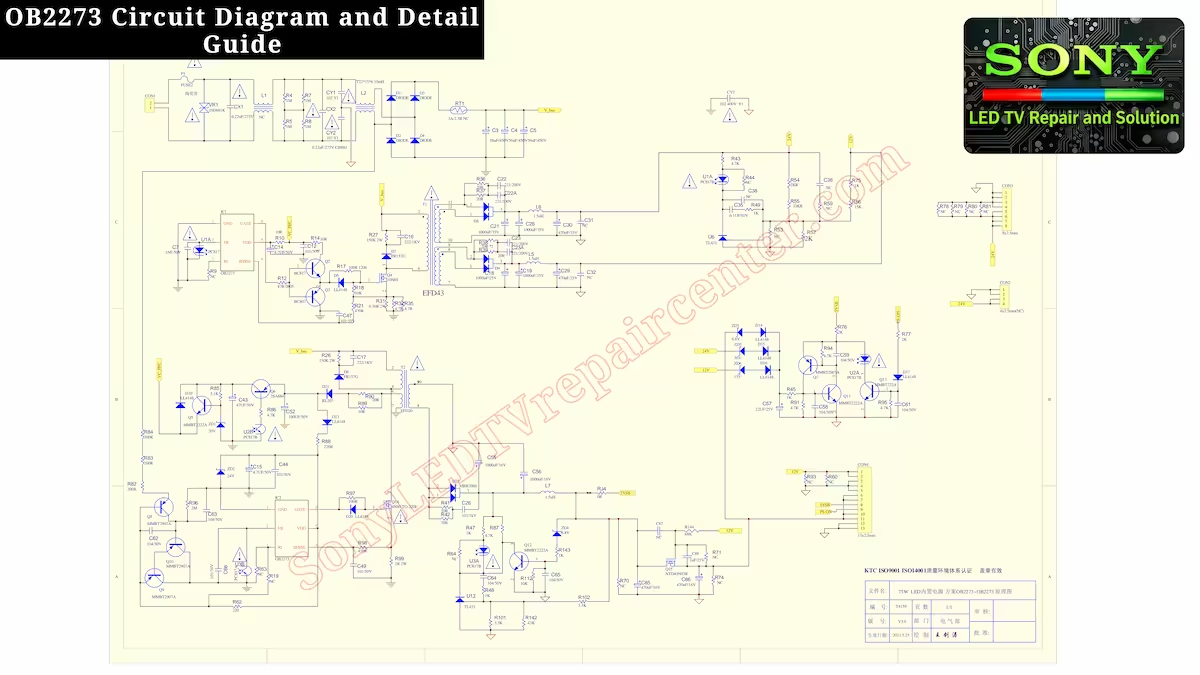
OB2273 Circuit Diagram and Detail Guide – In this article, we explain how the SMPS IC works, including its complete pinout, working principle, and practical applications. You will also learn about common faults, troubleshooting tips, and how to test and repair this IC in various power supply circuits. Whether you are a beginner or an experienced technician, this guide provides clear and detailed information to understand and repair OB2273-based power supplies effectively.
Working Principle of OB2273 IC
The OB2273 Circuit Diagram and Detail Guide introduces the OB2273 IC, a reliable and widely used SMPS controller that powers various electronic devices, from small LCD panels to larger LED displays. This IC efficiently converts and regulates voltage, ensuring each section of the power supply receives stable and accurate power. Its built-in protection features, including overvoltage, overcurrent, and thermal protection, make it highly dependable and safe for circuits. Technicians find the OB2273 particularly convenient because its pinout and working principle are straightforward, allowing easy fault finding and repairs. Its versatility, high efficiency, and dependable performance explain why the OB2273 remains a popular choice in display power supply designs.
Pin Description – IC: OB2273
- GNG – This pin serves as the ground reference for the IC, providing a stable voltage baseline for all internal circuits. Proper grounding through this pin ensures reliable operation and reduces noise or voltage fluctuations that could affect the power supply’s performance.
- FB – The Feedback (FB) pin monitors the output voltage and helps regulate the power supply. By comparing the output to a reference voltage, the IC can adjust switching activity to maintain stable voltage levels. If this pin detects incorrect voltage, it may cause the output to flicker or the device to shut down temporarily.
- RT – The RT pin is used to set the oscillator frequency of the IC. This frequency controls the switching speed of the SMPS, which directly affects efficiency and output stability. Incorrect connection or values here can lead to unstable voltages or excessive heat in the circuit.
- SENCE – The Sense (SENCE) pin monitors the current flowing through the primary side of the power supply. It protects the IC and the connected components from overcurrent conditions by signaling the IC to limit or stop switching when necessary.
- VDD – The VDD pin provides the main supply voltage to power the IC’s internal logic and control circuits. A stable voltage here is crucial for proper operation; if it drops or fluctuates, the IC may behave unpredictably or fail to start.
- GATE – The GATE pin drives the external switching transistor (typically a MOSFET) to control power delivery to the transformer. Proper functioning of this pin ensures correct timing and efficient power transfer, while issues can cause improper switching, overheating, or output voltage problems.
OB2273 Circuit Diagram – PDF View
You can zoom in to view the complete circuit clearly and scroll left or right to examine every section in detail.
Common Faults and Troubleshooting.
OB2273 IC is a highly integrated current mode PWM control IC. Its fault finding is very easy. If you have good knowledge about its working, then you will find this IC in some TCL models and mostly in the power supply of Chinese boards. It is a very popular number. Now let’s come to its common faults. Usually, the output voltage of its power supply gets blinking fault. This is due to the feedback problem of the IC. Check its feedback with an optocoupler. If the IC is blasted due to voltage spike or its VCC is showing short circuit from ground, then in this condition, along with changing the IC, pin number 3 which is the RT pin and pin number 4 which is to sense the current must also be replaced.
Conclusion
In this guide, OB2273 Circuit Diagram and Detail Guide has provided a complete overview of the OB2273 IC, including its circuit diagram, pinout, working principle, and common troubleshooting tips. By studying the OB2273 Circuit Diagram and Detail Guide, technicians can better understand the IC’s pin functions and how this SMPS controller operates, enabling them to quickly identify and resolve issues in various power supply circuits. This detailed guide equips both beginners and experienced technicians to handle OB2273-based circuits efficiently and confidently.
Sony KLV-32S400A 2 Blink Error Guide
Sony KDL-40W660E 6 Blinks Error Fix

Shaukat Ali has over 30 years of experience in LED TV repair, specializing in chip-level repair work. He is an expert in Sony LED TVs, and also repairs other major brands like Samsung, TCL, Orient, and Haier. His expertise includes display panel faults, motherboard issues, power supply circuits, T-Con, and HDMI faults. Based in Lahore, he shares real-time fault finding cases from daily repair work to help technicians and learners with practical experience.
📞 Contact: +92 321 4066054