
HV365WXC-200/206 COF & Scalar Test Points
If you are looking for 8656-FCYOB COF Data & Scalar Test Points, then this article will help you with complete and clear information related to LED TV COF (Chip-on-Film). Here we will only mention the COF number going forward, not the full title every time, so things stay simple and easy to follow. You will also get all test points in image form, which is useful during actual panel repair work.
Along with that, the panel numbers HV365WXC-200 / HV365WXC-206 are included in this article. We have also covered the complete scalar strip test points for this panel, so everything related to COF and scalar data is available in one place.
Along with that, the panel numbers HV365WXC-200 / HV365WXC-206 are included in this article. We have also covered the complete scalar strip test points for this panel, so all COF and scalar-related data is available in one place for technicians.
Role of COF in LED TV Panels
Chip-on-Film (COF) is a key part of an LED TV panel structure, especially on the side gate driver section. It is responsible for handling and distributing signals across the panel in a controlled way. In simple terms, COF works as a bridge between the panel and the display driving system.
Its main role is to manage signal distribution and voltage delivery for pixel operation. This helps in proper image formation on the screen by ensuring each pixel receives the required signal and voltage at the right time. In LED TV panels, especially side COF types, it plays an important role in stable display output and proper screen response.
8656-FCYOB COF Data Overview
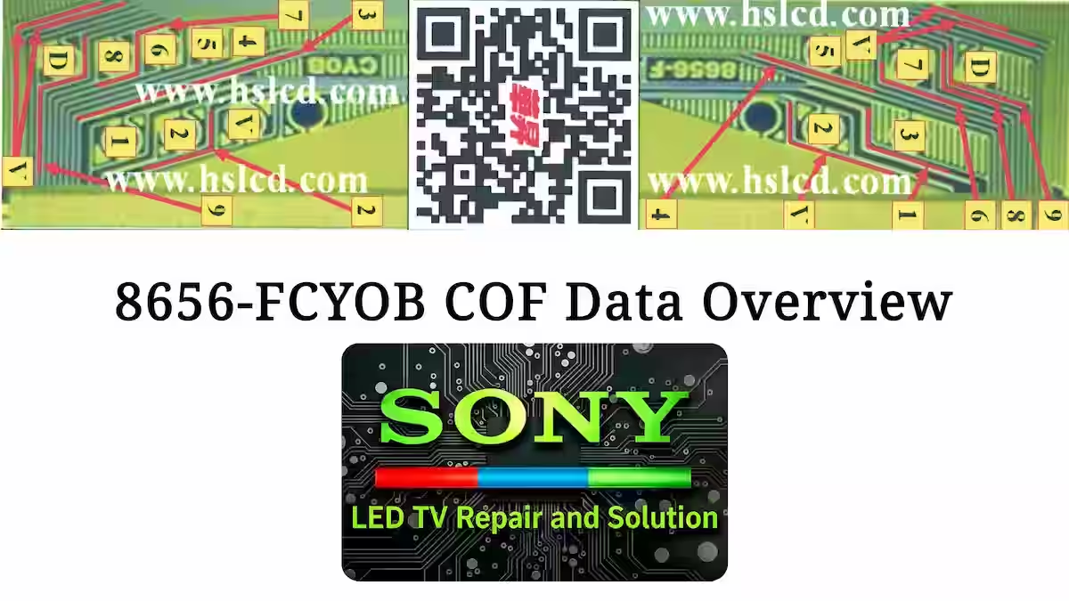
A clear reference for technicians is shown below for better understanding, where all test points for 8656-FCYOB COF Data & Scalar Test Points are clearly marked. In this image, you can easily follow the layout to identify signal flow, voltage distribution, and important checking areas on the COF. This visual diagram is added so you can quickly trace and test the COF section during panel repair work without any confusion.
HV365WXC-200-206 Scalar Strip Test Points
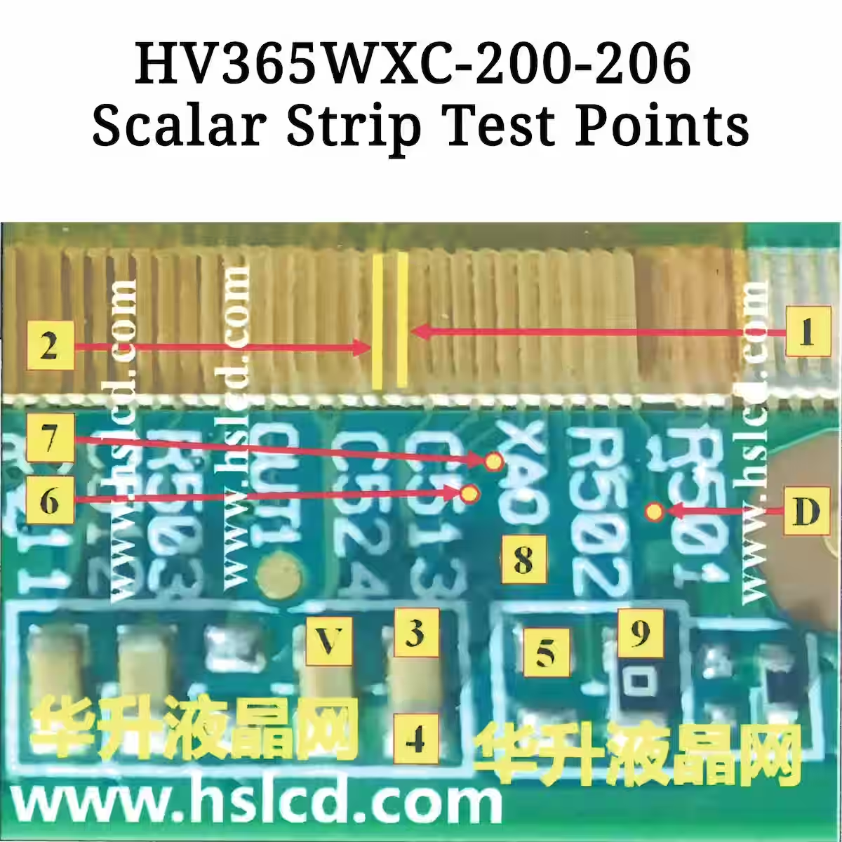
A detailed reference is provided below for technicians, where all scalar strip test points for HV365WXC-200 / HV365WXC-206 panel are clearly shown. In the image, you can easily trace each test point on the scalar strip, which helps in checking signal paths and voltage levels during panel troubleshooting. This visual layout is added to make the repair process more accurate and simple without any confusion.
8656-FCYOB COF Pin Description
- PIN 1 (VON +24.6V)
VON +24.6V is a high-level supply voltage used in the COF driving section of the panel. It supports the gate control circuit and ensures proper switching operation for display lines. During testing, this pin should remain stable at +24.6V, because any drop or fluctuation can lead to display issues like flickering or half screen faults.
- PIN 2 (VOFF -7.8V)
VOFF -7.8V is a negative supply voltage line used in the COF driving circuit of the panel. It helps in proper turn-off control of the gate driver section, ensuring clean switching between ON and OFF states. During testing, this pin should stay stable at -7.8V, as any variation or missing voltage can result in display instability, vertical lines, or improper panel response.
- PIN 3 (VDD +3.3V)
VDD +3.3V is a main logic supply voltage used in the COF section of the panel. It powers the internal control and signal processing circuits that manage data communication across the display. During testing, this pin should be stable at +3.3V, as any drop or fluctuation can cause no display, signal errors, or unstable panel operation.
- PIN 4 (GND)
GND is the main ground reference point in the COF circuit of the panel. It provides a return path for all supply voltages and keeps the overall circuit stable. During testing, this pin should show proper continuity with ground, as any poor connection or open ground can cause unstable voltages, signal disturbance, or complete panel failure.
- PIN 5 (STV 0.03V)
STV 0.03V is a start vertical signal line used in the COF driving section of the panel. It controls the vertical scanning sequence, ensuring proper line-by-line activation of pixels on the display. During testing, this pin should show a very low stable voltage around 0.03V, and any abnormal reading or signal loss can result in vertical display issues or no proper screen start-up.
- PIN 6 (CPV +1.6V)
CPV +1.6V is a clock pulse voltage line used in the COF driving circuit of the panel. It helps in generating and controlling timing signals for proper data shifting across the display lines. During testing, this pin should remain stable at +1.6V, as any fluctuation or missing clock signal can lead to display timing errors, flickering, or distorted image output.
- PIN 7 (OE1 1.1V)
OE1 1.1V is an output enable signal line used in the COF section of the panel. It controls the activation of the data output drivers, ensuring signals are passed correctly to the display pixels. During testing, this pin should show a stable voltage around 1.1V, as any irregularity or missing signal can cause display dimming, line errors, or partial screen issues.
- PIN 8 (XAO +3.2V)
XAO +3.2V is a signal voltage line used in the COF driving section of the panel. It plays an important role in internal data handling and signal coordination for proper display operation. During testing, this pin should remain stable at +3.2V, as any drop or fluctuation can cause signal mismatch, display distortion, or abnormal panel behavior.
- PIN 9 (SAO +3.2V)
SAO +3.2V is a signal output line used in the COF section of the panel. It helps in carrying processed data signals for proper display control and pixel operation. During testing, this pin should remain stable at +3.2V, as any voltage drop or instability can lead to signal errors, display distortion, or abnormal screen behavior.
- PIN D (STVD 0.02V)
STVD 0.02V is a vertical driver timing signal used in the COF section of the panel. It supports the vertical scanning process and helps in proper frame start control for the display. During testing, this pin should show a very low stable voltage around 0.02V, as any abnormal reading or missing signal can cause vertical display failure, no start condition, or line shifting issues.
- PIN V (VCOM +7.3V)
VCOM +7.3V is a common voltage reference used in the COF section of the panel. It plays a key role in stabilizing pixel operation and maintaining proper image balance on the screen. During testing, this pin should remain stable at +7.3V, as any fluctuation or incorrect level can cause flickering, washed colors, or unstable display performance.
Conclusion
This article on 8656-FCYOB COF Data & Scalar Test Points is prepared to give technicians a clear and practical reference for real repair work. In this guide, we have covered detailed COF pin information along with their exact voltage levels, which helps in understanding how each line works inside the panel. The main focus is to make testing simple and accurate, especially when working on LED TV COF-related faults.
Along with COF data, the panel numbers HV365WXC-200 / HV365WXC-206 are also included, and the scalar strip test points have been clearly explained with visual reference support. All information in this article is arranged in a way that helps in quick troubleshooting, signal tracing, and voltage checking without confusion during actual panel repair.
Related Articles
If you want to read more of our Chip-on-Film (COF) reference articles, you can check the links given below. These articles will help you understand different COF data, test points, and panel troubleshooting guides in a simple and practical way for real repair work.
8658-HC528 – Read More
NT39538H-C1272A – Read More
KD-49XF8000 2 Blink Error Fix Guide
Sony KDL-40W600B No Power Fault Guide
BD9397EFV Backlight Driver Guide

Shaukat Ali has over 30 years of experience in LED TV repair, specializing in chip-level repair work. He is an expert in Sony LED TVs, and also repairs other major brands like Samsung, TCL, Orient, and Haier. His expertise includes display panel faults, motherboard issues, power supply circuits, T-Con, and HDMI faults. Based in Lahore, he shares real-time fault finding cases from daily repair work to help technicians and learners with practical experience.
📞 Contact: +92 321 4066054