
MP3398AGF Circuit, Pinout & Voltage Details
MP3398A IC Circuit Diagram — in this article, we are sharing the complete circuit diagram of this LED driver IC so its working can be understood in a practical way. This is a four-channel LED driver IC, which means it can operate four separate LED strings, commonly used in LED TV backlight circuits. Along with this, we will explain the pin connections in detail so you can easily identify each pin and take accurate measurements during troubleshooting. We will also cover the protection system of this IC, explaining how it protects the circuit under different fault conditions like over-voltage or open LED, and helps prevent damage.
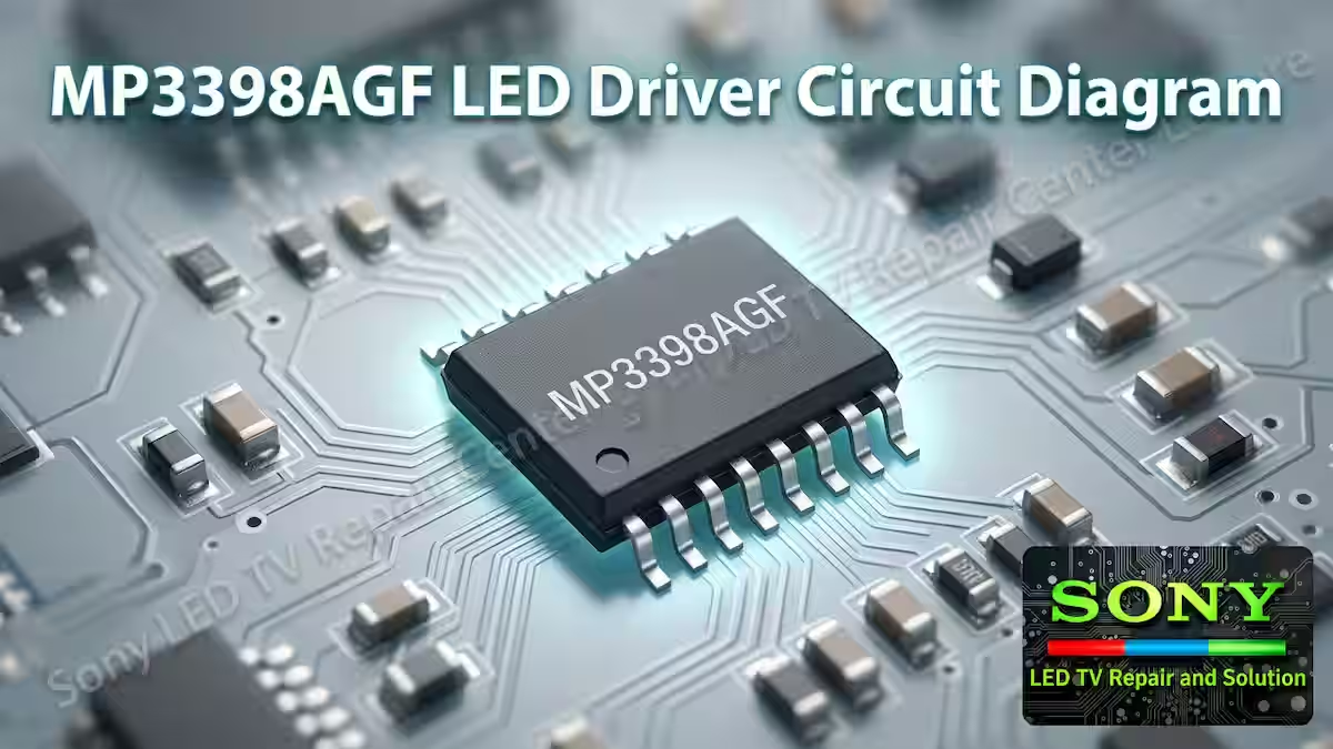
MP3398A Features
The MP3398A is a 4-string WLED driver IC capable of delivering up to 350mA current per string, making it suitable for LED TV backlight applications. It operates within a wide input voltage range of 5V to 28V, ensuring stable performance in different power conditions. This IC provides high accuracy with around 2.5% current matching between LED strings, which helps maintain uniform brightness. It supports both PWM and analog dimming modes, along with a programmable switching frequency for flexible operation.
The IC also allows cascading with a single power source, which is useful in multi-driver designs. For protection, it includes built-in features such as LED open and short protection, programmable over-voltage protection, over-current protection, thermal shutdown with auto recovery, inductor and diode short protection, and under-voltage lockout. The MP3398A is available in SOIC-16, TSSOP-16EP, and SOIC-20 packages, making it practical for different circuit designs and repair work.
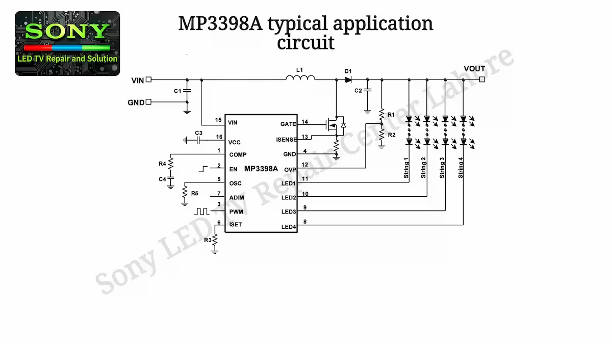
MP3398A Typical Application Circuit
The image below shows the typical application circuit of the MP3398A IC Circuit Diagram, explaining how it operates in a real LED TV backlight system. In this circuit, the LED strings are connected to the output channels of the IC, where each string is driven independently to maintain proper current balance and uniform brightness. The input supply section, inductor, and external components are clearly arranged to support stable operation of the driver. You can also see the feedback and control pins used for current regulation and protection purposes. This typical application helps in understanding the practical working of the IC, especially during fault finding and circuit analysis in LED TV repair.
MP3398A Pin Description (SOIC-16)
Pin 1 (COMP)
The COMP pin of the MP3398A LED driver IC is used as the output of the error amplifier and for the compensation network. It plays an important role in stabilizing the feedback control loop of the IC and ensures smooth and stable LED current regulation. This pin continuously adjusts the control signal according to changes in LED load conditions, helping to maintain stable current flow and preventing fluctuations or oscillations in the output. It also indirectly influences PWM control and overall brightness stability of the LED strings. During fault diagnosis, any abnormal voltage or unstable behavior at the COMP pin can indicate issues such as flickering backlight or unstable LED current regulation.
Pin 2 (EN)
The EN (Enable) pin of the MP3398A LED driver IC is used to turn the IC ON or OFF. When this pin receives a proper high signal, the IC starts operation and enables the LED driver stages. If the EN pin is low or not properly biased, the IC remains in shutdown mode and no output is generated.
This pin is commonly controlled by the main system or power management section of the LED TV. It plays an important role in power sequencing and system control, ensuring the backlight only operates when all conditions are normal. During troubleshooting, if the EN signal is missing or unstable, the IC will not start, resulting in a no-backlight condition even if all other voltages are present.
Pin 3 (PWM)
The PWM pin of the MP3398A LED driver IC is used for brightness control of the LED backlight. It receives a PWM (Pulse Width Modulation) signal from the main board or control circuit, which adjusts the duty cycle to increase or decrease the LED brightness smoothly.
This pin allows precise dimming control without affecting LED current stability. When the PWM signal is present and stable, the backlight brightness responds correctly according to the input signal. If the PWM signal is missing, weak, or unstable, it can result in dim display, flickering, or no backlight condition depending on the circuit design.
Pin 4 (GND)
The GND pin of the MP3398A LED driver IC is the ground reference point for the entire IC. It provides the return path for current and ensures stable operation of all internal circuits.
All internal control, regulation, and protection circuits use this pin as a common reference level. A poor or weak ground connection can cause unstable operation, abnormal voltages, or complete failure of the IC to start. During troubleshooting, proper continuity and low resistance to ground should always be confirmed for correct operation of the driver circuit.
Pin 5 (OSC)
The OSC pin of the MP3398A LED driver IC is used to set the internal oscillator frequency of the IC. This frequency controls the switching operation of the LED driver and directly affects efficiency, noise level, and overall performance of the backlight circuit.
By using an external resistor or capacitor network (depending on circuit design), the switching frequency can be programmed through this pin. A stable oscillator signal is important for proper operation of all LED channels. If there is any fault or abnormal condition at the OSC pin, it can result in improper switching, flickering display, or complete failure of the backlight operation.
Pin 6 (ISET)
The ISET pin of the MP3398A LED driver IC is used to set the reference current for the LED channels. By connecting an external resistor to this pin, the maximum LED current for each string is programmed according to the circuit requirement.
This pin plays an important role in controlling overall brightness and power management of the backlight system. A change in the ISET resistor value directly affects the LED current level, which can increase or decrease brightness. During fault finding, an incorrect value or open connection at the ISET pin can result in very low brightness, uneven backlight, or complete loss of proper LED current regulation.
Pin 7 (ADIM)
The ADIM pin of the MP3398A LED driver IC is used for analog dimming control of the LED backlight. It adjusts the LED current level by varying the analog voltage applied to this pin, allowing smooth brightness control without affecting the switching frequency.
The ADIM pin of the MP3398A LED driver IC is used for analog dimming control of the LED backlight. It adjusts the LED current level by varying the analog voltage applied to this pin, allowing smooth brightness control without affecting the switching frequency.
This pin is often used together with PWM dimming to achieve more precise brightness adjustment in LED TV backlight systems. When a proper analog control voltage is present at ADIM, the brightness changes smoothly according to the input level. If this signal is missing or unstable, it can result in fixed brightness, dim display, or improper backlight control.
Pin 8 (LED4)
The LED4 pin of the MP3398A LED driver IC is one of the four output channels used to drive the LED string. This pin provides regulated current to the fourth LED string in the backlight system, ensuring uniform brightness along with the other channels.
Each LED output channel is controlled independently, but all are regulated together to maintain current balance between strings. During operation, this pin works under constant current control as set by the ISET and feedback circuitry. If there is any fault such as open LED string or short circuit in this channel, it can trigger protection mode or result in dim or no backlight condition on that section of the panel.
Pin 9 (LED3)
The LED3 pin of the MP3398A LED driver IC is the output channel used to drive the third LED string in the backlight system. It provides regulated constant current to ensure stable and uniform brightness across the connected LEDs.
This channel works in coordination with the other LED output pins to maintain proper current matching between all strings. If the LED3 string has an open circuit, short LED, or any abnormal load condition, it can activate the protection circuit or cause uneven backlight performance. During troubleshooting, checking voltage and current behavior at this pin helps in identifying faults related to the third LED string.
Pin 10 (LED2)
The LED2 pin of the MP3398A LED driver IC is used as the output channel for the second LED string in the backlight system. It supplies regulated constant current to ensure stable and uniform brightness for that specific LED string.
This pin operates along with the other LED output channels to maintain proper current balance across all strings. Any issue such as open LED, short circuit, or abnormal load in the LED2 line can trigger protection mode or result in uneven backlight. During fault finding, checking voltage and response at this pin helps identify problems related to the second LED string.
Pin 11 (LED1)
The LED1 pin of the MP3398A LED driver IC is the output channel for the first LED string in the backlight system. It delivers regulated constant current to ensure stable brightness and proper operation of the connected LED string.
This pin works together with the other LED output channels to maintain balanced current across all strings for uniform backlight performance. If there is any issue such as an open LED, short circuit, or abnormal load in the LED1 line, it can trigger protection mode or cause uneven or missing backlight. During troubleshooting, checking the voltage and behavior at this pin helps in identifying faults in the first LED string.
Pin 12 (OVP)
The OVP (Over Voltage Protection) pin of the MP3398A LED driver IC is used to monitor the output voltage of the boost stage. It ensures that the LED driver does not exceed the safe operating voltage limit.
When the voltage rises above the set threshold, this pin triggers the protection mechanism and helps prevent damage to the IC as well as the LED backlight circuit. This feature is important for panel safety, especially during open LED conditions or feedback failures. If there is any issue with the OVP pin or its sensing network, it can lead to shutdown behavior, no backlight condition, or improper protection triggering.
Pin 13 (ISENSE)
The ISENSE pin of the MP3398A LED driver IC is used to monitor the LED current flowing through the circuit. It senses the current feedback signal and sends it to the internal control system for proper regulation.
This pin plays a key role in maintaining constant current across all LED strings and ensuring uniform brightness. Based on the signal from ISENSE, the IC adjusts its output to keep the current stable under different load conditions. If there is any issue such as open sensing resistor, poor connection, or abnormal signal at this pin, it can result in incorrect current regulation, flickering, or protection mode activation.
Pin 14 (GATE)
The GATE pin of the MP3398A LED driver IC is used to drive the external switching MOSFET in the boost converter stage. It provides the necessary gate drive signal to turn the MOSFET ON and OFF during switching operation.
This switching action controls the energy transfer from the input supply to the LED output stage, making it a key part of the boost regulation system. A proper waveform at the GATE pin is essential for correct circuit operation. If this signal is weak, missing, or distorted, it can lead to no boost output, low backlight, or complete failure of the LED driver circuit.
Pin 15 (VIN)
The VIN pin of the MP3398A LED driver IC is the main supply input pin. It receives the DC voltage from the power source that is used to operate the internal circuitry of the IC.
This voltage is essential for proper functioning of all control sections inside the driver, including the oscillator, protection circuits, and current regulation system. If the VIN supply is missing, unstable, or too low, the IC will not start working, and the LED backlight circuit will remain off. Common issues at this pin include dry solder joints, blown supply path, or voltage drop due to faulty components in the input line.
Pin 16 (VCC)
The internal 6V linear regulator output (VCC) is used to provide a stable and regulated supply for the IC’s internal control circuitry as well as for driving the external MOSFET gate. This regulated voltage plays an important role in ensuring proper switching operation and reliable performance of the LED driver stage.
A ceramic capacitor is connected between the VCC pin and ground to act as a bypass and filtering component. This capacitor helps to remove high-frequency noise, smooth out voltage fluctuations, and maintain a stable DC level for the internal circuits.
This stable VCC supply is essential for correct operation of the gate driver section and the internal logic of the IC. If this capacitor becomes weak, open, or leaky, or if there is any disturbance on the VCC line, it can lead to improper gate drive signals, unstable switching, flickering of the backlight, or even complete shutdown of the driver circuit.
Layout Consideration
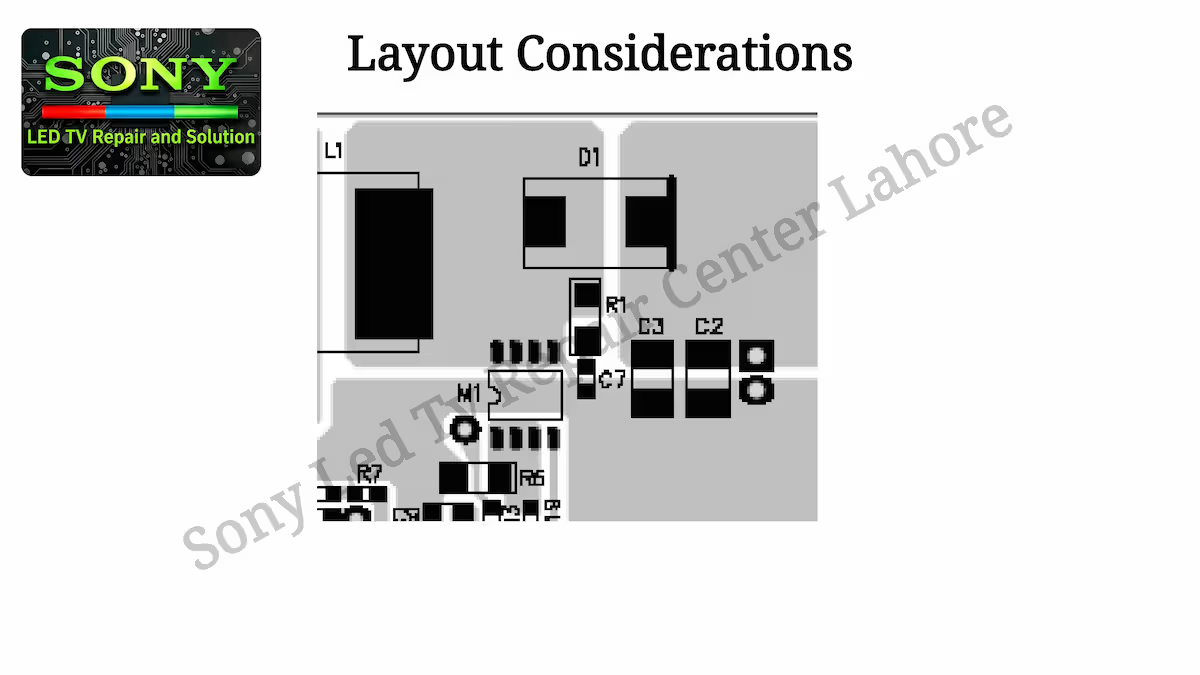
The circuit layout for the MP3398A requires special attention in order to minimize EMI noise and ensure stable operation of the LED driver circuit. The high-frequency switching paths must be carefully designed to avoid interference and performance issues.
The current loop formed by the external MOSFET (M1), the output diode (D1), and the output capacitors (C2, C3) carries high-frequency pulse currents. This loop should be kept as small, short, and direct as possible to reduce switching losses, noise generation, and electromagnetic interference.
All logic and control signals are referenced to the signal ground. To further improve noise performance, it is recommended to separate the power ground (PGND) from the signal ground (GND). After proper separation, both grounds should be connected at a single point to ensure correct grounding and stable circuit operation, as shown in the layout image provided below.
MP3398A IC Circuit Diagram
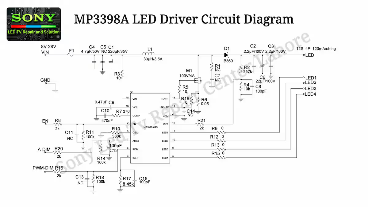
The following section presents the complete and optimized circuit diagram of the MP3398A IC LED driver stage. This diagram is carefully arranged to clearly explain the full working structure of the circuit, making it easier for technicians to understand the actual operation and signal flow.
In this circuit diagram, all important components such as resistor values, capacitor ratings, external MOSFET switching stage, output diode network, and control sections are properly shown with their complete connections. This helps in accurate analysis, fault finding, and practical troubleshooting of the LED driver circuit, and below you can view the complete image which contains the full schematic along with all component values and the detailed working configuration of the MP3398A IC circuit.
MP3398A IC Repairing Tips
When working on this circuit, many technicians try to find a shortcut by directly forcing the protection circuit or bypassing it to power ON the board. A common practice is that they take the capacitor connected on Pin 1 (COMP) and try to ground it through a 10k resistor to start the circuit. This is not a correct method and can be harmful for the IC and surrounding components. Instead, proper fault finding should always be done by tracing the actual issue step by step until the real faulty section is identified.
Another important section in this circuit is the voltage divider network connected to the feedback and over-voltage protection path, especially related to Pin 12 (OVP). This section determines the operating voltage level of the circuit and also controls how much voltage is allowed for safe operation. In most cases, the resistors used in this voltage divider become faulty or drift from their original value, which leads to incorrect voltage regulation or protection triggering. These resistors should always be checked carefully during troubleshooting.
The third critical point is the ISENSE section on Pin 13, which is connected through a low-ohm resistor from the MOSFET source. This resistor plays a key role in defining the current (amperes) of the entire LED driver circuit. In the given circuit, it is often labeled as R19, but its value can vary depending on the design. Normally, it is around 470 ohms to 500 ohms or slightly different in some boards. If this resistor value changes or becomes open, it can directly affect the output current and overall LED brightness, so it must always be verified during repair.
Conclusion
The MP3398A IC Circuit Diagram and its complete working can be properly understood only when each section is analyzed step by step, from pin configuration to practical circuit behavior. This IC may look simple, but its protection system, feedback control, and current regulation make it a sensitive and important part of the LED driver circuit.
For reliable repair, it is always better to avoid shortcuts and focus on accurate measurements, proper signal tracing, and understanding of each section such as COMP, OVP, and ISENSE. When these key areas are checked correctly, most backlight faults can be diagnosed easily. A technician who follows proper troubleshooting methods will not only fix the fault faster but also avoid repeated failures in the same circuit.
Related IC Guides
If you want to explore more detailed guides like this, you can check our complete collection of LED driver IC repair and fault finding articles. We regularly share practical circuit explanations, pin details, and troubleshooting methods to help technicians work more efficiently. You can find all related posts in our [IC Guides & Schematics].
Sony KDL-40W600B No Power Fault Guide

Shaukat Ali has over 30 years of experience in LED TV repair, specializing in chip-level repair work. He is an expert in Sony LED TVs, and also repairs other major brands like Samsung, TCL, Orient, and Haier. His expertise includes display panel faults, motherboard issues, power supply circuits, T-Con, and HDMI faults. Based in Lahore, he shares real-time fault finding cases from daily repair work to help technicians and learners with practical experience.
📞 Contact: +92 321 4066054