
Test Points with V500HJ1-PE8 C3 Panel
Struggling to find the right test points on V500HJ1-PE8 C3 panel? In this practical guide, we are sharing the complete package including NT61305H-C52A3A COF data and scaler step test points — along with real images of the COF data that you can see and match with your panel. Exactly what every LED technician needs. No theory, only real data and real pictures for real repairs.
Panel-V500HJ1-PE8 C3
Along with this, there are also PCB Panel-V500HJ1-PE8 C3 connections which will help you in tracing the data. You can easily compare the data and PCB. This will help you a lot. This data is being shared to help the pure league technician. If you download the PDF and keep it with you, it will be of great benefit to you.
Role of Side COF in Panel
Side COF (also known as Gate COF) is responsible for controlling the rows of the panel. While the source COF sends video data to the columns, the side COF sends scanning signals like VGH, VGL, CKV, and STV to turn the rows on and off one by one. Without the side COF, the panel would not know which row to activate at which time. In simple words, the source COF gives the data, and the side COF gives the timing. Both work together to create a complete image. If the side COF fails, you will see horizontal lines, half display, flickering, or a completely dead panel.
NT61305H-C52A3A COF Data Overview
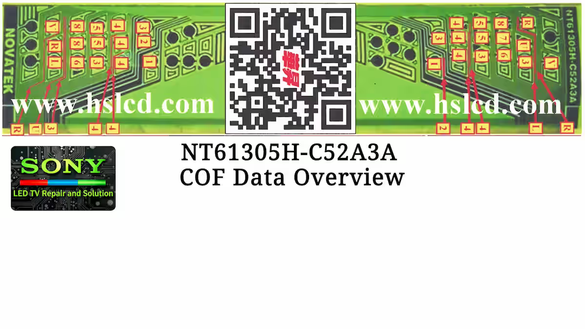
Below is the real image of the NT61305H-C52A3A COF data. In this picture, you can clearly see all the test points of this COF including input, output, and ground points. Every pin and signal location is marked properly so that you can understand and identify them easily. Please note that the complete scaler strip test points (left and right side) will be shared in the next images below. You can take help from those images as well for your fault finding and troubleshooting during actual repair work.
V500HJ1-PE8 C3 Right Scalar Strip Test Points
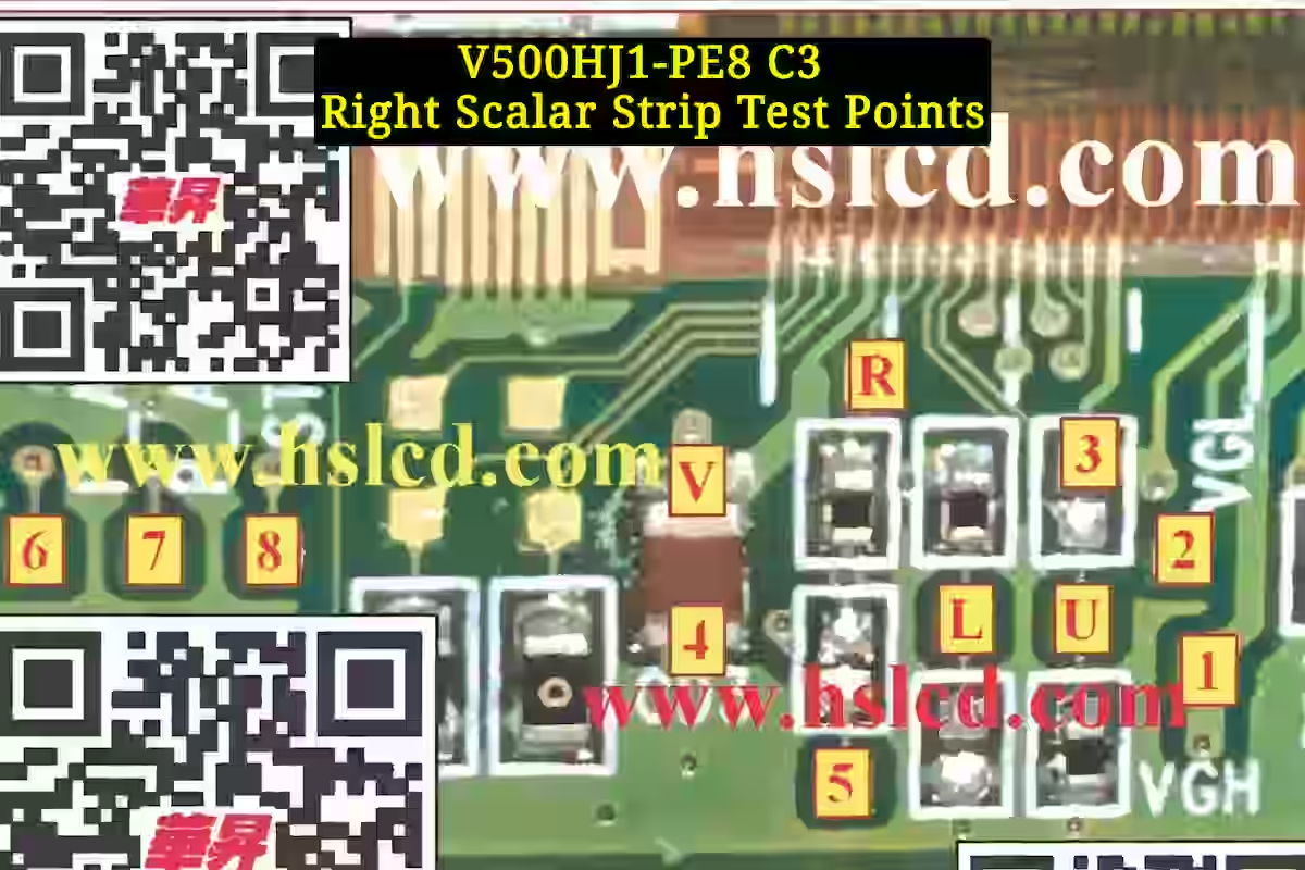
Below is the real image of the right side scalar strip test points for the V500HJ1-PE8 C3 panel. In this image, you can see the complete test points of the right side scalar strip. Every test point is clearly marked so that you can easily examine them with the COF data. By using this image, you can perform proper troubleshooting, bypass the panel if needed, test voltages, and check signals during your repair work. Keep this image as a reference for right side fault finding.
V500HJ1-PE8 C3 Left Scalar Strip Test Points
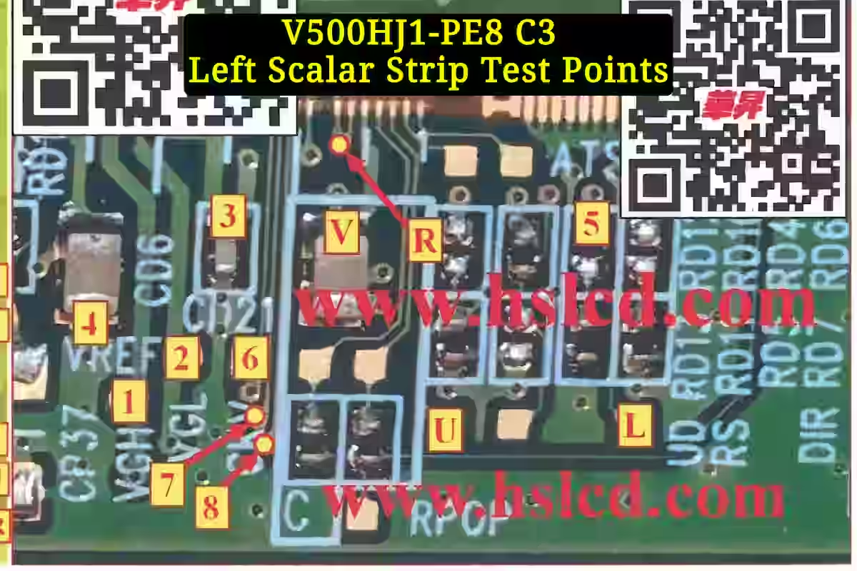
Here is the real image of the left side scalar strip test points for the same V500HJ1-PE8 C3 panel. In this image, you will find the complete left side scalar strip test points clearly marked for practical use. Just like the right side, you can examine these test points with the NT61305H-C52A3A COF data. Use this image to troubleshoot left side faults, test voltages and signals, bypass the panel, or verify continuity. Having both left and right side images will give you a complete reference for your repair work.
My Experience
Care & Technical Issue
My advice for every technician is to handle this panel with extreme care while working on it. It is a very delicate thing. Now coming to the technical part — often, the VGH and VGL tracks inside the glass get shorted with each other. Most technicians try to bypass this short.
Proper Solution & Common Mistake
From my experience, if the short is inside the glass, you need to cut both tracks from the glass side and also from the COF side. Only then you can properly bypass them. The common mistake I have seen is that technicians cut only one track and bypass from one side only. As a result, the panel works for some time and then fails again. The proper solution is to cut both tracks from both ends and then bypass.
Test Point Description with Functions
- Pin 1: VGH = +26.8V
VGH turns on the TFTs inside the panel for row scanning. If this voltage is missing or disturbed, the panel will show no display, vertical lines, or a completely black screen.
- Pin 2: VGL = -7.8V
VGL is the gate-off voltage that turns off the TFTs properly. If this voltage is missing or unstable, the panel will show ghosting, image retention, or horizontal lines.
- Pin 3: VDD = +3.3V
VDD is the logic supply voltage for the timing controller and COF IC. If this voltage is missing or low, the panel will not turn on or will show no display at all.
- Pin 4: GND (Ground)
GND is the common ground reference for all voltages on the COF and panel. If GND is loose or broken, all other voltages will become unstable and the panel will not work properly.
- Pin 5: STV = 0.02V (approximately 0V, but may pulse during operation)
STV (Start Pulse Vertical) is the vertical start pulse that tells the panel when to begin scanning each frame. It is a timing signal, not a DC voltage. If STV is missing, the panel will show no display, garbled image, or the picture may shift vertically.
- Pin 6: CKV = +1.8V
CKV is the vertical clock signal that shifts the gate pulses line by line. If this signal is missing or weak, the panel will show horizontal lines, double image, or no proper scanning.
- Pin 7: OE2 = +1.2V
OE2 (Output Enable 2) controls the timing of the gate output signals. It helps turn off the gate drivers at the right time. If this signal is missing or unstable, the panel may show flickering, ghosting, or uneven brightness.
- Pin 8: OE1 = +1.2V
OE1 (Output Enable 1) works with OE2 to manage the gate driver timing. It ensures clean switching between rows. If this signal is disturbed, the panel may show horizontal lines, image sticking, or random flickering.
- Pin 9: U = 0V
U is a reserved or unused pin on this COF. It may be connected to ground internally or left open. No function is assigned to this pin. No effect on panel performance.
- Pin L: L/R = +3.3V (or 0V depending on panel configuration)
L/R (Left/Right) selects the scanning direction of the panel. When set to +3.3V, scanning starts from the left side. When set to 0V, scanning starts from the right side. If this pin is disconnected or floating, the panel may scan from the wrong side or show a mirrored image.
- Pin R: STVR = 0.03V (approximately 0V, pulses during operation)
STVR (Start Pulse Vertical Right) is the vertical start pulse for the right side of the panel. It works together with STV to control scanning from the right side. If this signal is missing, the right side of the panel may show no display, vertical lines, or incomplete scanning.
- Pin V: VCOM = +7.1V
VCOM is the common reference voltage for the liquid crystal layer. It helps maintain a stable image and prevents flickering. If this voltage is off or unstable, the panel will show severe flickering, color distortion, or screen flashing.
Conclusion
The NT61305H-C52A3A COF data shared in this article is a complete practical guide for anyone working on the V500HJ1-PE8 C3 panel. We have covered all the important test points including VGH, VGL, VDD, STV, CKV, OE1, OE2, L/R, STVR, and VCOM along with their voltages and functions. Real images of the COF data and both left and right scalar strip test points have also been included.
From my experience, proper bypassing of VGH and VGL tracks requires cutting both tracks from both ends — otherwise the panel will fail again. Keep this article saved for your future repairs and always handle the panel with care.
Related Articles
If you want to read more articles related to chip-on-film data and panel repair, please check the links below. We have shared practical guides for different COF models and panel types. Keep learning and keep repairing.
NT61303H-C52A2B COF Data 3–Read more
NT61312H-C6518A-A COF Data–Read more
Sony Bravia 1.8V Power Supply Fault Guide
Sony Bravia 3.3V Power Supply Fault Guide

Shaukat Ali has over 30 years of experience in LED TV repair, specializing in chip-level repair work. He is an expert in Sony LED TVs, and also repairs other major brands like Samsung, TCL, Orient, and Haier. His expertise includes display panel faults, motherboard issues, power supply circuits, T-Con, and HDMI faults. Based in Lahore, he shares real-time fault finding cases from daily repair work to help technicians and learners with practical experience.
📞 Contact: +92 321 4066054