
KLV-40W652D 1.2V Core Voltage Line Details
In this Sony Bravia 1.2V Power Supply Fault Guide, we are going through the MediaTek processor-based power section voltage lines in a proper series format so that both beginners and field technicians can get practical benefit. In this series, we have already covered the 5V Power Supply Detail, 3.3V Power Supply Fault Guide, and 1.5V Power Supply Fault Guide in separate articles. Now continuing the same sequence, this article focuses on the 1.2V Power Supply Fault Guide, which is a very important core voltage line for the MediaTek IC. The main purpose is to understand each voltage line step by step so fault finding becomes easier and confusion is reduced.
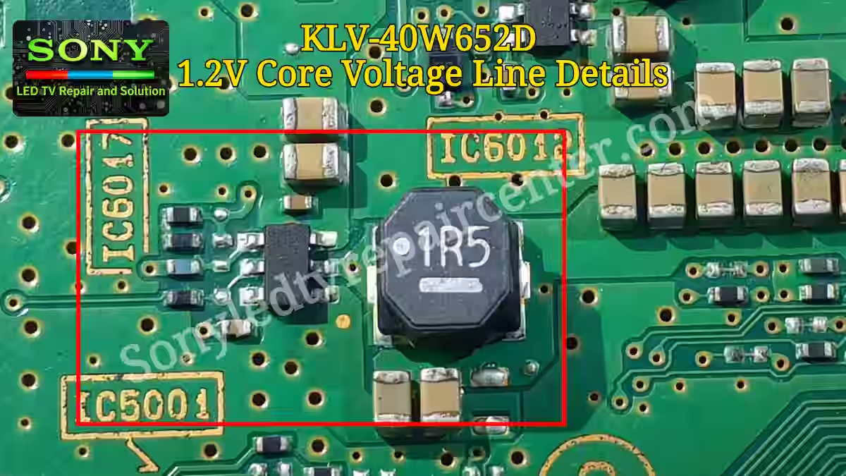
KLV 40W652D 1.2V Core Voltage
The 1.2V core voltage is a very critical supply line in the MediaTek processor section used in Sony Bravia TVs. This voltage is mainly responsible for powering the core functions of the CPU, keeping the internal processing stable, and ensuring that the system runs basic operations without any interruption. If this 1.2V line drops, becomes unstable, or is completely missing, the TV may fail to boot properly, or it can get stuck on the logo screen during startup.
Inside the MediaTek IC, this core voltage supports the internal logic circuits, processing units, and essential system control blocks. That is why this line plays a very important role in overall system performance. In fault finding cases, this voltage cannot be ignored, especially in situations like no power, dead boot, or logo hang issues.
KLV 40W652D 1.2V Input Supply Path
1.2V regulator in Sony Bravia KLV 40W652D does not generate voltage on its own; it depends on the main 5V power supply line. This 5V line is the primary input source for the regulator section. From here, the voltage is fed into the step-down circuit where it is processed and converted into a stable 1.2V core voltage for the MediaTek IC.
If this 5V input is missing or unstable, the 1.2V regulator will not function properly, and the core voltage will drop completely. In practical fault finding, when the TV shows no boot or dead condition, the first check point is always the 5V supply feeding into this regulator section before moving further into the core voltage side.
1.2V Regulator Pinout and Voltage Details
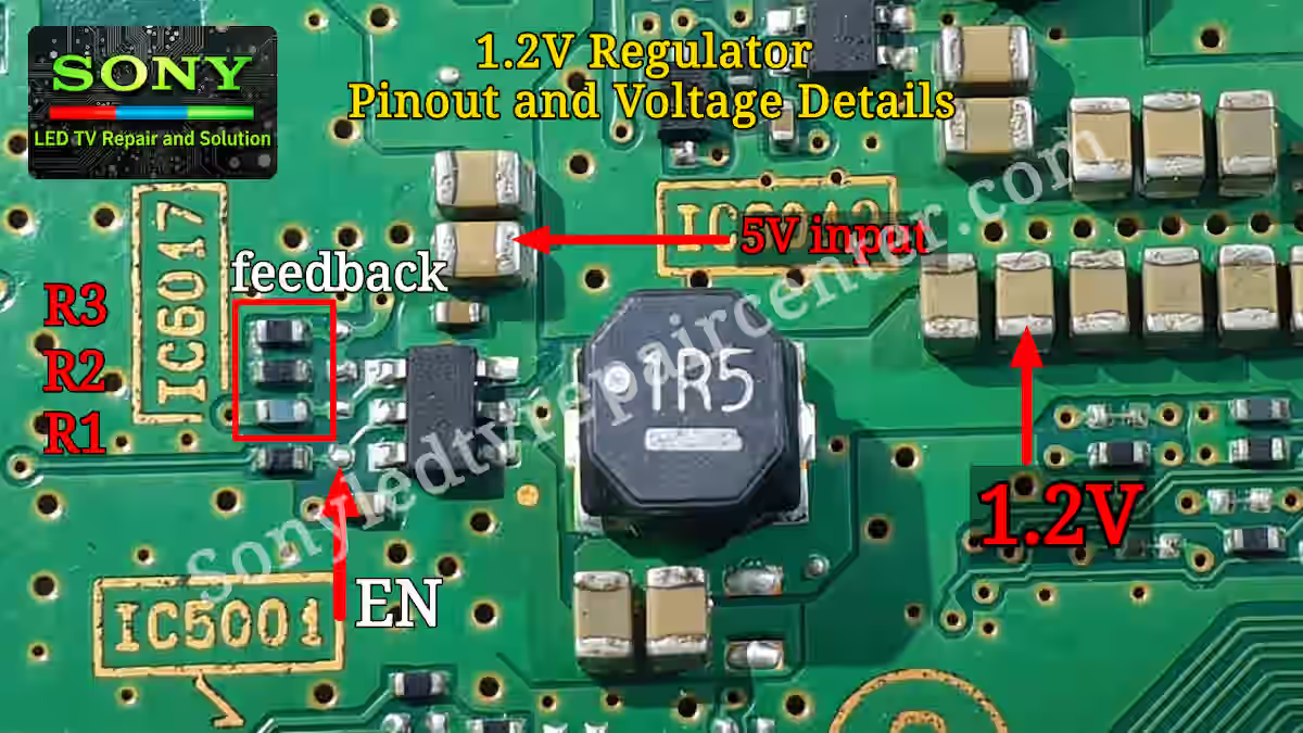
This 1.2V regulator section in Sony Bravia KLV 40W652D uses a small SMD step-down IC, designed in a compact package with three pins on one side and three pins on the other side. It works as the main buck converter to generate stable 1.2V core voltage for the MediaTek processor.
Pin 1 of this IC is ground, which is directly connected to the main chassis ground. Pin 2 is the XL (switching) pin, where an external inductor coil is connected. This coil plays a key role in stepping down the voltage and generating the required 1.2V output. After this stage, capacitors are placed on the output side to smooth and filter the voltage, ensuring a clean supply for the MediaTek IC without ripple or noise.
Pin 3 is the main 5V input supply pin, which feeds power into the regulator IC. Without this input, the regulator cannot operate. Pin 4 is the feedback (FB) pin, which controls and stabilizes the output voltage. This feedback network consists of three resistors labeled as R1, R2, and R3. R2 and R3 are connected in series from the output side and return the divided voltage back to the feedback pin, while R1 is connected from the feedback pin to ground. This resistor divider network is responsible for maintaining the correct 1.2V output level.
Pin 5 is the enable (EN) pin, which activates the IC when the system allows it to run. If this pin is not enabled, the regulator will remain off even if input voltage is present. Pin 6 has a capacitor connected to it, which helps in further stabilizing the internal operation of the regulator circuit.
Overall, this step-down IC (ICS6 type) plays a very important role in generating the 1.2V core voltage required for the MediaTek processor. Any fault in input supply, feedback network, or inductor stage can directly affect system boot and cause no display or dead condition issues.
My Practical Experience in This Section
From practical fault finding experience in this 1.2V regulator section, most of the issues are commonly found in the feedback network. The main problem I have observed is with the feedback voltage divider resistors (R1, R2, and R3). Over time, these resistors often drift in value, and due to this variation, the output voltage drops to a very low level. In some cases, I have seen the output going as low as around 0.82V instead of the required 1.2V level, which directly affects the system startup. In such situations, replacing these resistors becomes necessary, although their exact values are covered in a separate article.
Another important point from my experience is that the 6-pin buck converter IC itself can also become faulty. When this IC is damaged, the output voltage either does not generate at all or becomes unstable and passes incorrect voltage levels. This condition can also create risk for the MediaTek IC, as improper voltage may affect its performance or even cause damage. That is why the feedback section of this regulator circuit is extremely critical, and technicians must always pay close attention to the correct resistor values and stable feedback operation during fault diagnosis.
Conclusion
In this Sony Bravia 1.2V Power Supply Fault Guide, we clearly understood the importance of the 1.2V core voltage line and how it plays a critical role in the MediaTek processor operation in KLV 40W652D. This section is not just a simple voltage stage, but a key part of system stability where even a small fluctuation can lead to boot failure or no display condition. From practical fault findings, the feedback network and regulator IC behavior must always be checked carefully because most issues are directly linked to these points. Proper understanding of this section makes troubleshooting much faster and more accurate for any technician working on Sony Bravia boards.
Related article
For better understanding of the complete voltage sequence in Sony Bravia KLV 40W652D, you can also check the following related guides:
- Sony Bravia 5V Power Supply Detail – Read More
- Sony Bravia 3.3V Power Supply Fault Guide – Read More
- Sony Bravia 1.5V Power Supply Fault Guide – Read More
Sony KDL-40W600B No Power Fault Guide

Shaukat Ali has over 30 years of experience in LED TV repair, specializing in chip-level repair work. He is an expert in Sony LED TVs, and also repairs other major brands like Samsung, TCL, Orient, and Haier. His expertise includes display panel faults, motherboard issues, power supply circuits, T-Con, and HDMI faults. Based in Lahore, he shares real-time fault finding cases from daily repair work to help technicians and learners with practical experience.
📞 Contact: +92 321 4066054