
KLV-40W652D – Tuner Stage 1.8V Voltage Line
this Sony Bravia 1.8V Power Supply Fault Guide, we are continuing our voltage detail series by focusing on the tuner stage in KLV-40W652D, where the 1.8V line plays an important role in signal processing and overall tuner performance. This series is designed to give both beginners and field technicians a clear, practical understanding of how different voltage lines work inside Sony Bravia boards. As part of this sequence, we have already covered key sections like the 3.3V power supply fault guide, which explains the logic supply side in detail. Now in this article, we move one step further to understand how the 1.8V regulator works in the tuner section and why this voltage is critical during fault finding.
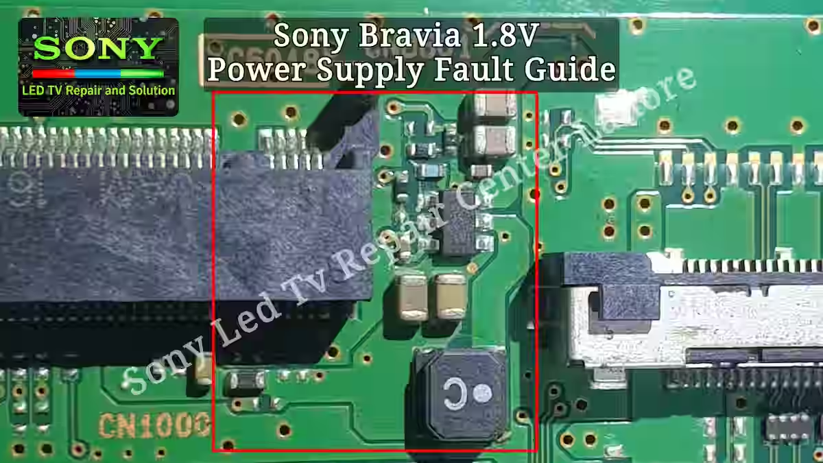
KLV 40W652D 1.8V Power Supply Section
In Sony Bravia KLV 40W652D, the 1.8V power supply is mainly used for the tuner stage, where stable voltage is required for proper signal processing and channel handling. This voltage is generated through the MP1470 IC, which works as a step-down (buck) converter in this section. The IC receives its input supply from the main power line (usually 5V or 3.3V depending on board design), and then steps it down to a regulated 1.8V output.
This 1.8V output is specifically directed towards the tuner section, ensuring stable operation of tuner-related circuits. If this voltage is missing or unstable, the tuner may fail to function properly, resulting in issues like no signal, channel tuning problems, or complete loss of RF input. That is why checking the input supply to the MP1470 IC and verifying its 1.8V output is a key step during fault finding in this section.
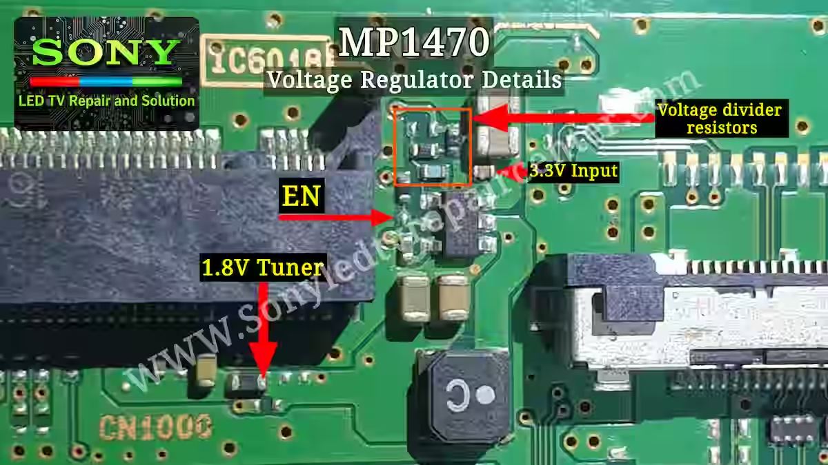
MP1470 Regulator Pinout
The MP1470 IC used in this section is a step-down (buck) regulator that converts the 5V input supply into a stable 1.8V output for the tuner stage. This IC works with a compact 6-pin configuration, where each pin has a specific role in voltage regulation and control.
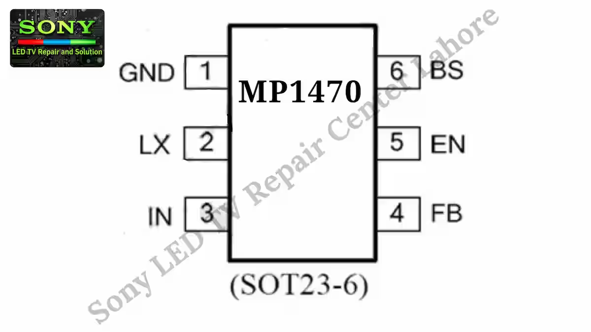
Pin 1 of the IC is GND, which is connected to the main ground of the board. Pin 2 is the LX (switching pin), where an external inductor is connected to generate the output voltage. Pin 3 is the input pin (VIN), where the 5V supply is applied to the IC. From this input, the IC performs the step-down process to produce the required 1.8V output.
Pin 4 is the feedback (FB) pin, which is connected to a resistor divider network from the output side. This feedback circuit is responsible for maintaining a stable 1.8V output by continuously monitoring and adjusting the voltage level. Pin 5 is the EN (enable) pin, which controls the ON/OFF state of the IC. When this pin is active, the regulator starts working.
Pin 6 is the BS (bootstrap) pin, where a capacitor is connected to support the internal switching operation of the IC. This pin helps drive the switching circuit efficiently during operation.
Overall, the MP1470 IC steps down the 5V input to a regulated 1.8V output using its switching and feedback mechanism. Any fault in input supply, feedback network, or LX section can directly affect the tuner voltage and lead to signal-related issues.
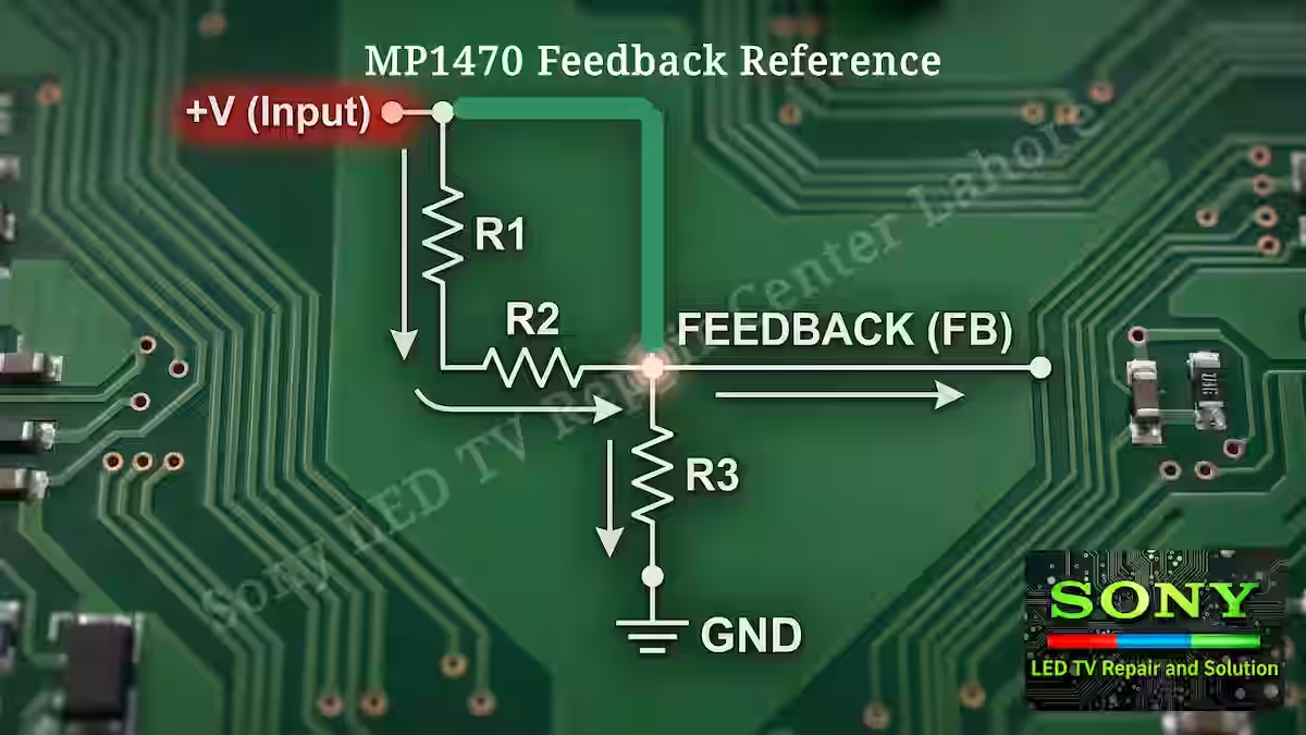
MP1470 – Feedback Reference
MP1470 is a voltage regulator IC and its feedback system plays a very important role in controlling the output voltage. In this circuit, a voltage divider network is used to take a sample from the output and send it to the feedback pin. This allows the IC to continuously monitor the output voltage and keep it stable.
When the output voltage increases, the feedback voltage also rises accordingly, and the IC reduces its switching activity. Similarly, when the voltage drops, the IC increases its duty cycle to bring the output back to the normal level. In the image given below, this voltage divider feedback network is clearly shown, which helps the whole system maintain proper regulation and stability.
Practical Experience in 1.8V Section
From practical repair experience on Sony Bravia KLV 40W652D, tuner section faults are quite common, and in many cases the issue is linked to the 1.8V regulator section. One of the most frequent problems I have observed is in the feedback network of the MP1470 IC. The feedback resistors (voltage divider) often get disturbed or change their values, which causes the output voltage to drop below the required 1.8V level. When this happens, the tuner does not function properly and may result in no signal or tuning issues.
In some cases, I have also seen that the tuner module itself becomes faulty and needs replacement. Since this tuner is installed separately in a slot, it can be replaced easily when required. Apart from this, I have also experienced cases where the MP1470 IC itself gets damaged and stops regulating properly, resulting in no 1.8V output or unstable voltage behavior. In such situations, replacing the IC becomes necessary.
However, before replacing the tuner or IC, it is very important to properly check the 1.8V supply and especially the feedback section. This feedback network consists of three resistors forming a voltage divider, which we have clearly highlighted in the image below. Technicians should always pay close attention to this section, as it is a key point in fault diagnosis.
Conclusion
In this Sony Bravia 1.8V Power Supply Fault Guide, we clearly understood the working and importance of the 1.8V tuner stage supply in KLV 40W652D. This voltage is generated through the MP1470 regulator section, which plays a key role in maintaining stable operation of the tuner circuit. From practical fault finding, we have seen that issues in the feedback network, regulator IC, or even the tuner module itself can directly affect the 1.8V line and cause no signal or tuning failures. Proper testing of input, output, and feedback section is always necessary for accurate diagnosis. This guide helps technicians to understand the real working behavior of the 1.8V section and improve fault tracing in Sony Bravia boards.
Related Articles
If you want to explore more articles in this voltage series and understand other important power supply sections of Sony Bravia KLV 40W652D, you can check the related guides below.
Sony Bravia 5V Power Supply Detail – Read More
Sony Bravia 1.2V Power Supply Fault Guide – Read More
Sony Bravia 1.5V Power Supply Fault Guide – Read More
KD-49XF8000 2 Blink Error Fix Guide
Sony KLV-40W652D 3 Blink Error Fix Guide

Shaukat Ali has over 30 years of experience in LED TV repair, specializing in chip-level repair work. He is an expert in Sony LED TVs, and also repairs other major brands like Samsung, TCL, Orient, and Haier. His expertise includes display panel faults, motherboard issues, power supply circuits, T-Con, and HDMI faults. Based in Lahore, he shares real-time fault finding cases from daily repair work to help technicians and learners with practical experience.
📞 Contact: +92 321 4066054