
V420HJ2-P01 C3 Panel – Complete Test Points
NT61303H-C52A2B DATA SHEET provides the complete technical details for the COF used with the V420HJ2-P01 C3 panel. In this article, you will find full COF pin connections, voltage levels, channel numbers, and all scaler strip test points clearly mentioned. This guide is prepared for technicians working on this specific panel and its C3 version who need accurate and practical reference data. The complete information for this panel variant is organized here in one place to make testing, troubleshooting, and verification easier and more reliable.
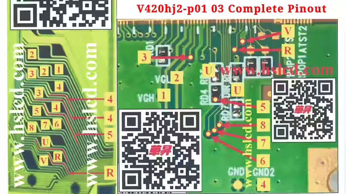
V420HJ2-P01 C3 Panel – Complete Pinout
Below, we will explain the complete test points and voltage details of the V420HJ2-P01 C3 panel in a clear and practical way. This includes the scaler strip connections as well as the COF (Chip on Film) information, so technicians can understand both sections together. Each test point will be listed with its voltage value and function, making it easier to verify signals and perform accurate troubleshooting step by step.
1: VGH – +26.3V
This pin provides the high gate voltage (VGH) necessary to drive the TFTs on the LCD panel. It ensures that the pixels switch correctly and maintain proper brightness and contrast. If VGH is missing, unstable, or deviates from the required +26.3V, you may notice flickering, uneven brightness, or blank areas on the display. To resolve this, check the VGH supply circuit, including the voltage regulator and associated resistors or transistors, and ensure proper connections to the COF. Measuring the voltage directly at the COF pin can help verify stability and pinpoint any faulty components.
2:VGL – -7.8V
This pin provides the low gate voltage (VGL) for the TFTs on the LCD panel, controlling the off-state of pixels to maintain proper contrast and prevent unwanted conduction. If VGL is missing, too low, or fluctuates, the display may show ghosting, dark or bright stripes, or uneven contrast across the screen. To fix this issue, check the VGL supply circuit, including any resistors, transistors, and voltage regulators, and ensure correct connection to the COF pin. Direct measurement of VGL at the COF pin helps confirm proper voltage and stability.
3:VDD – +3.3V
This pin supplies the main logic voltage (+3.3V) to the LCD panel, powering the internal circuits of the COF and ensuring proper signal processing. If VDD is absent, unstable, or outside the expected range, the panel may fail to display any image, show random flickers, or become completely unresponsive. To resolve this, check the VDD supply line, voltage regulator, and any related capacitors or resistors. Measuring the voltage directly at the COF pin confirms whether the logic circuits are receiving stable power.
4:GND – 0V
This pin serves as the ground reference for all voltages on the LCD panel, providing a stable return path for current and ensuring proper operation of the COF circuits. If GND is disconnected or has poor contact, the panel may display flickering, unstable signals, or fail to power on correctly. To fix this, check all ground connections, solder joints, and the continuity between the COF ground pin and the main PCB ground. Ensuring a solid ground connection is crucial for reliable panel operation.
5:STV – +0.03V
This pin provides the Start of Vertical signal (STV) for the LCD panel, which initiates the vertical scanning of pixels for proper frame timing. If STV is missing, unstable, or incorrect, the display may show vertical lines, flickering, or misaligned rows. To resolve this, check the STV signal line, associated resistors or capacitors, and the COF connection. Measuring the voltage at the COF pin ensures that the vertical timing signal is accurate, keeping the panel display stable and properly synchronized.
6:CKV – +1.8V
This pin provides the clock signal for the LCD panel, controlling the timing of data transfer to the COF and ensuring accurate pixel driving. If CKV is missing, unstable, or distorted, the display may show horizontal lines, image tearing, or synchronization issues. To resolve this, check the clock signal source, associated resistors or capacitors, and the connection to the COF pin. Using an oscilloscope to verify a clean and stable clock waveform helps ensure proper panel operation.
7:OE1 – +1.1V
This pin functions as the Output Enable signal for the first section of the LCD panel, controlling when pixel data is actively driven to the display. If OE1 is missing, stuck high/low, or unstable, you may notice blank sections, flickering, or incomplete image rendering in that part of the screen. To fix this, check the OE1 signal line, related resistors or transistors, and its connection to the COF. Measuring the voltage at the COF pin while the panel is operating can help confirm proper signal timing.
8:OE2 – +1.1V
This pin serves as the Output Enable signal for the second section of the LCD panel, controlling the timing of pixel data output to ensure proper display operation. If OE2 is missing, unstable, or outside the expected voltage range, parts of the screen may appear blank, flicker, or show incomplete images. To resolve this, inspect the OE2 signal line, associated resistors or transistors, and the COF connection. Measuring the voltage at the COF pin during operation helps confirm that the OE2 signal is stable and functioning correctly.
U‑UD – +3.3V / 0V
This pin controls the Up/Down scanning direction of the panel, determining the vertical data sequence for proper image orientation. If the U‑UD signal is missing, unstable, or incorrect, the display may show inverted images, misaligned rows, or distorted vertical patterns. To fix this, check the U‑UD signal line, related resistors or transistors, and the COF connection. Verifying the voltage at the COF pin ensures that the scanning direction signal is accurate and the panel displays correctly.
R:STVR – 0.04V
This pin provides the Reset signal for the right-side vertical scanning (R‑STVR) of the LCD panel, ensuring proper alignment and timing of vertical lines in that section. If R‑STVR is missing, unstable, or deviates from 0.04V, you may notice vertical stripes, misaligned rows, or flickering on the right portion of the display. To fix this, check the R‑STVR signal line, associated resistors or capacitors, and the COF connection. Verifying the voltage at the COF pin ensures the vertical reset signal is stable and the panel operates correctly.
V:VCOM – +7.6V
This pin provides the common voltage (VCOM) for the LCD panel, which stabilizes the liquid crystal layer and ensures uniform pixel operation across the display. Proper VCOM is critical for consistent brightness, contrast, and preventing flickering. If V‑VCOM is missing, unstable, or deviates from +7.6V, the display may show ghosting, flickering, or uneven brightness. To fix this, check the VCOM supply circuit, related resistors or capacitors, and the COF connection. Measuring the voltage directly at the COF pin helps confirm stability and proper panel operation.
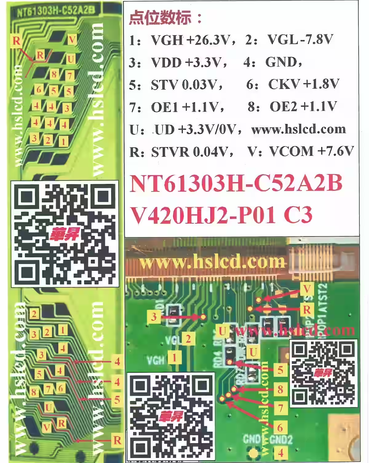
V420HJ2-P01 C3 – COF & Scaler Overview
The image below provides a complete overview of the COF (Chip on Film) for the V420HJ2-P01 C3 panel, including all scaler strip connections, pin assignments, and test points. Every voltage line, channel signal, and COF pin is clearly labeled, giving technicians a full reference for testing, troubleshooting, and verifying the panel. This detailed illustration ensures that all critical points are visible in one place, making it easier to identify and measure each connection accurately while working on this panel variant.
Conclusion:
The NT61303H-C52A2B DATA SHEET is published by Sony LED TV Repair Center to assist technicians in understanding and servicing the V420HJ2-P01 C3 panel. It provides a reliable reference for COF pin connections, voltages, channel numbers, and scaler strip test points, making troubleshooting and verification easier and more accurate.
This comprehensive DATA SHEET ensures that all critical information for the V420HJ2-P01 C3 panel is clearly documented. By following the details in this NT61303H-C52A2B DATA SHEET, technicians can perform precise troubleshooting, verify signals effectively, and maintain the panel efficiently, making it an essential resource for anyone working on this panel variant.
BD8174MUV Step up DC/DC Converter guide
SONY KD-49X7D All Blink Error Codes Guide
Sony Bravia 6 Blink Error Solution

Shaukat Ali has over 30 years of experience in LED TV repair, specializing in chip-level repair work. He is an expert in Sony LED TVs, and also repairs other major brands like Samsung, TCL, Orient, and Haier. His expertise includes display panel faults, motherboard issues, power supply circuits, T-Con, and HDMI faults. Based in Lahore, he shares real-time fault finding cases from daily repair work to help technicians and learners with practical experience.
📞 Contact: +92 321 4066054