
Complete LED Blink Error Codes of KD-49X7D
In this detailed guide on SONY KD-49X7D All Blink Error Codes Guide, we will thoroughly explain all LED blink codes for this model. Each blink code indicates a specific type of internal fault, and understanding them is crucial for accurate troubleshooting. For every code, we will describe its possible causes, the effects it can have on the TV’s operation, and the step-by-step solutions to resolve the issue. This comprehensive approach ensures that technicians can quickly identify problems, take the right corrective actions, and restore the TV to optimal performance efficiently.
Self Diagnosing SONY KD-49X7D
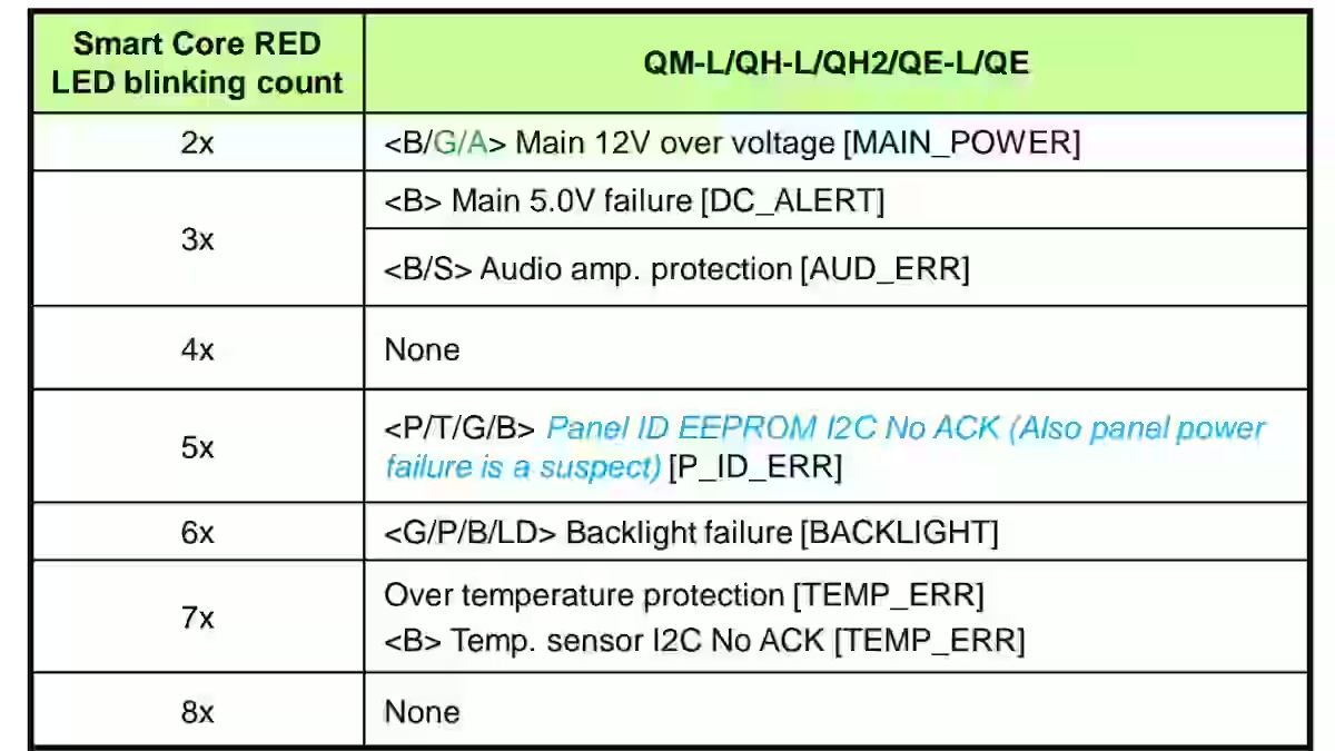
The self-diagnosing feature in the SONY KD-49X7D LED TV is designed to help technicians quickly identify and troubleshoot internal faults by using the built-in LED blinking codes. When the TV detects an abnormal condition, it automatically generates a specific number of blinks on the standby LED, each representing a distinct fault type. This system allows for efficient fault isolation without the need for extensive manual testing, saving both time and effort.
The blinking codes cover a wide range of potential issues, including power supply anomalies, main board or audio amplifier protection faults, panel communication errors, backlight failures, and temperature-related problems. By consulting the self-diagnosing chart, technicians can determine the general area of the problem and take appropriate corrective action, whether it involves checking voltage lines, replacing a faulty component, or addressing a communication issue between the main board and other sections.
This feature not only improves repair efficiency but also reduces the risk of misdiagnosis, ensuring that the TV is serviced correctly the first time. It is an essential tool for any technician working on SONY KD-49X7D models, providing a structured and systematic approach to fault detection and resolution.
2 – Blink Error Code – G Board Section
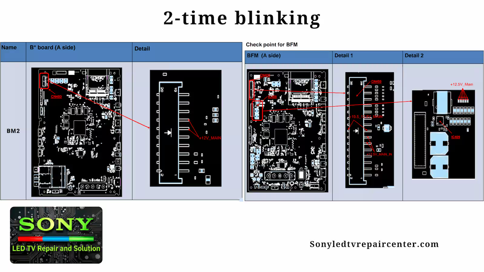
The Two Blink Error Code in the SONY KD-49X7D is an important diagnostic indicator specifically related to the G Board (Main Power Supply / BFM Board) section. When the standby LED flashes twice, it signals that the TV has detected a voltage irregularity in the main power line. Technicians should check the “+12V_MAIN_IN” voltage at pins 11 and 13 of CN400 on the BFM Board. If the voltage exceeds 13.2V, it indicates a potential overvoltage condition that may affect the board’s operation. Accurate measurement and diagnosis at this stage are crucial, as they allow the technician to determine whether the G Board itself is faulty or if other components in the main power circuit are contributing to the issue. By following this procedure, the root cause of the Two Blink Error can be identified efficiently, ensuring the TV is repaired correctly and restored to stable performance.
2 – Blink Error Code – AC Adapter Section
2 Blinks – AC Adapter indicate a voltage irregularity in the AC Adapter section of the BFM Board. To diagnose, technicians should first check the “+12V_Main” voltage across resistors R516 or R517 on the BFM Board. If the voltage exceeds 13.2V, it points to a potential overvoltage issue that can affect the board’s operation.
If the voltage is within normal range, the next step is to check the “+19.5_12.5V_MAIN” voltage at pins 15 and 16 of CN400 on the BFM Board, focusing on IC409 and surrounding components. Accurate testing at these points allows the technician to determine whether the AC Adapter itself or the associated circuitry is causing the Two Blink Error. Following this structured diagnostic procedure ensures precise fault identification and efficient repair, restoring the TV to stable performance.
3 – Blink Error Code – DC alert
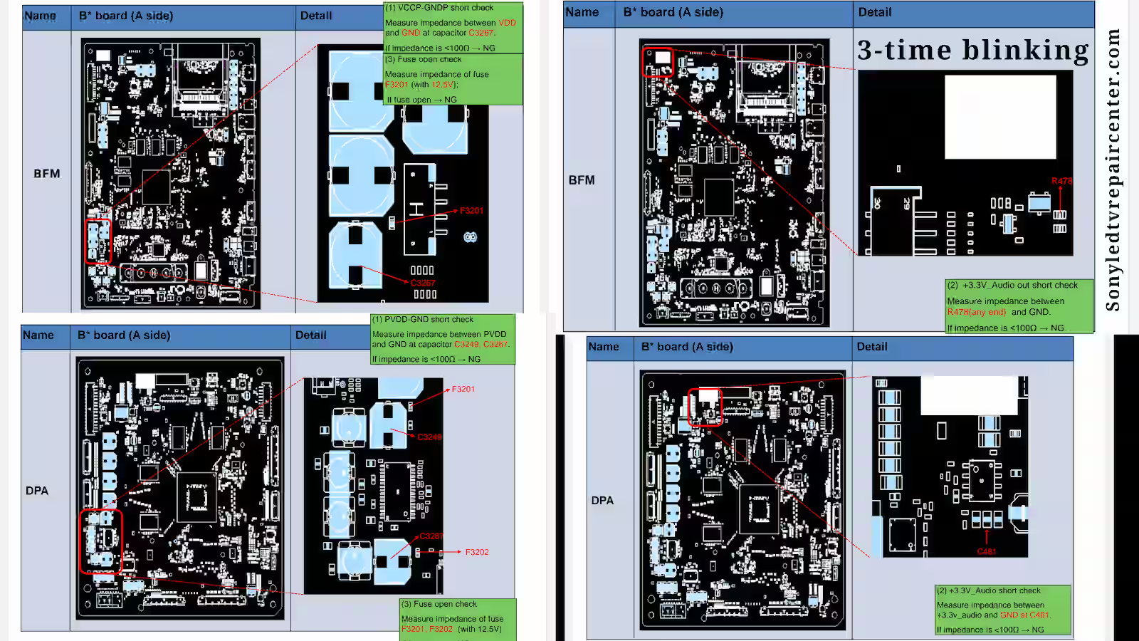
3 Blinks – Voltage Check indicates a potential fault in the B* Board related to the +5.0V_VBUS supply. Technicians should measure the voltage at capacitor C431, which should fall within the range of 4.959V to 5.285V. Any deviation outside this range signals a possible power supply issue on the B* Board. Performing this voltage check accurately helps determine whether the fault is related to the power line itself, allowing the technician to take corrective measures before further investigating other components.
3 – Blink Error Code – Audio Section
3 Blinks – Audio Error indicates a fault in the TV’s audio circuit. When the standby LED flashes three times, technicians should first measure the speaker impedance using a multimeter. If the impedance is less than 3Ω, the speaker must be replaced. If the speaker is functioning correctly, the next step is to check the B-PWB for possible VDD-GND or +3.3V_Audio shorts, as well as a blown fuse.
Additionally, technicians should verify that the 12.5V supply is momentarily provided to the B-PWB before the 3x blinking occurs. If any of these checks fail, appropriate replacements of the speaker harness or related PWB components should be made. Following this step-by-step procedure ensures accurate diagnosis of the audio circuit fault and restores proper audio functionality to the SONY KD-49X7D LED TV.
4 – Blink Error Code – LD Error
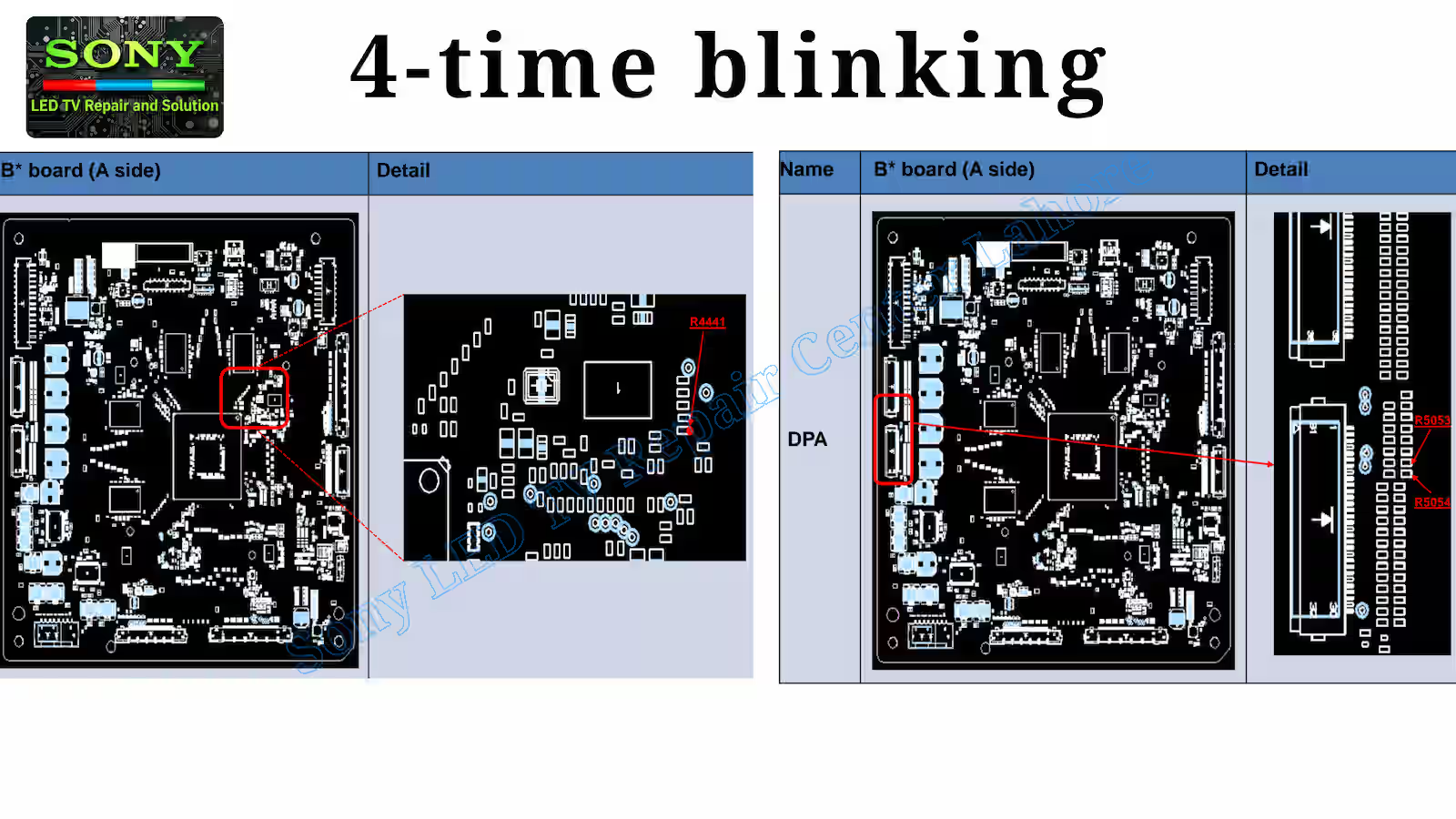
4-Blinks – LD Error indicates a fault related to the LD (Line Driver / LED Driver) control circuit in the Sony KD-49X7D LED TV. When the standby LED flashes four times, technicians should check the “LD_ERR” signal at resistor R4441 (page 3) on the DPA Board. This signal helps determine whether the error is being triggered by the LED driver section or a related control board such as the 4KBE SW or BM2 board configuration.
If the “LD_ERR” line remains at a High (“H”) state, it confirms that the protection circuit has detected a malfunction in the LED driving system. In this condition, the recommended corrective action is replacement of the DPA Board after verifying related connections and board conditions. Proper inspection of this signal ensures accurate diagnosis of the four-blink condition and prevents unnecessary replacement of other boards.
4 – Blink Error Code – BE_SCL1 / SDA1_LD
The second diagnostic step for the 4 Blinks – LD Error in the Sony KD-49X7D LED TV involves checking the ground impedance of the BE_SCL1 and SDA1_LD lines on the DPA Board. These lines are part of the communication path between the main control section (4KBE SW or BM2 board configuration) and the LD board.
Technicians should measure the ground impedance of both lines to determine whether a short or abnormal resistance is present. If an issue is detected, resistors R5053 and R5054 must be inspected carefully. A damaged or open resistor should be replaced. If the resistors are confirmed to be normal but the fault persists, the next step is to check and, if necessary, replace the LD board.
If all related components on the DPA and LD sections test normal, further inspection of the 4KBE SW or BM2 board may be required. This structured diagnostic approach ensures accurate fault isolation and prevents unnecessary board replacement while resolving the four-blink condition efficiently.
5 – Blink Error Code – T-Con / Panel
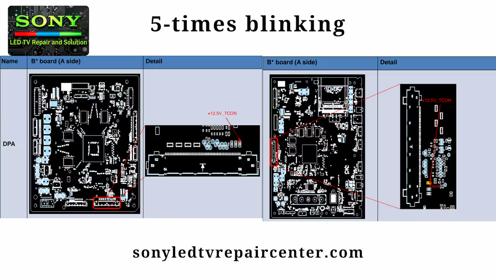
5 Blinks in the Sony KD-49X7D LED TV indicate a fault associated with the T-Con power line or panel communication circuit. When the standby LED flashes five times, the first step is to check the “+12.5V_TCON” voltage at resistor R5243 on the DPA board. If this voltage is missing or unstable, the issue may be related to the power supply path between the G Board and DPS board, and the harness connecting these boards should be inspected or replaced if suspicious.
If the power line is normal, attention should move to the V-By-One FFC cable, which carries high-speed panel signals. A loose, damaged, or improperly seated FFC can trigger the five-blink protection. If replacing the harness or FFC does not improve the symptom, the panel (T-Con section) itself may be defective and should be considered for replacement.
If no improvement is observed after these checks, the G Board should be examined and replaced if found faulty. In BM2 + DPA configurations, if the condition persists, the DPA board may be suspicious, and replacement may be required. This systematic diagnostic process ensures accurate isolation of the fault and prevents unnecessary replacement of major components while resolving the five-blink condition efficiently.
6 – Blink Error Code – Backlight
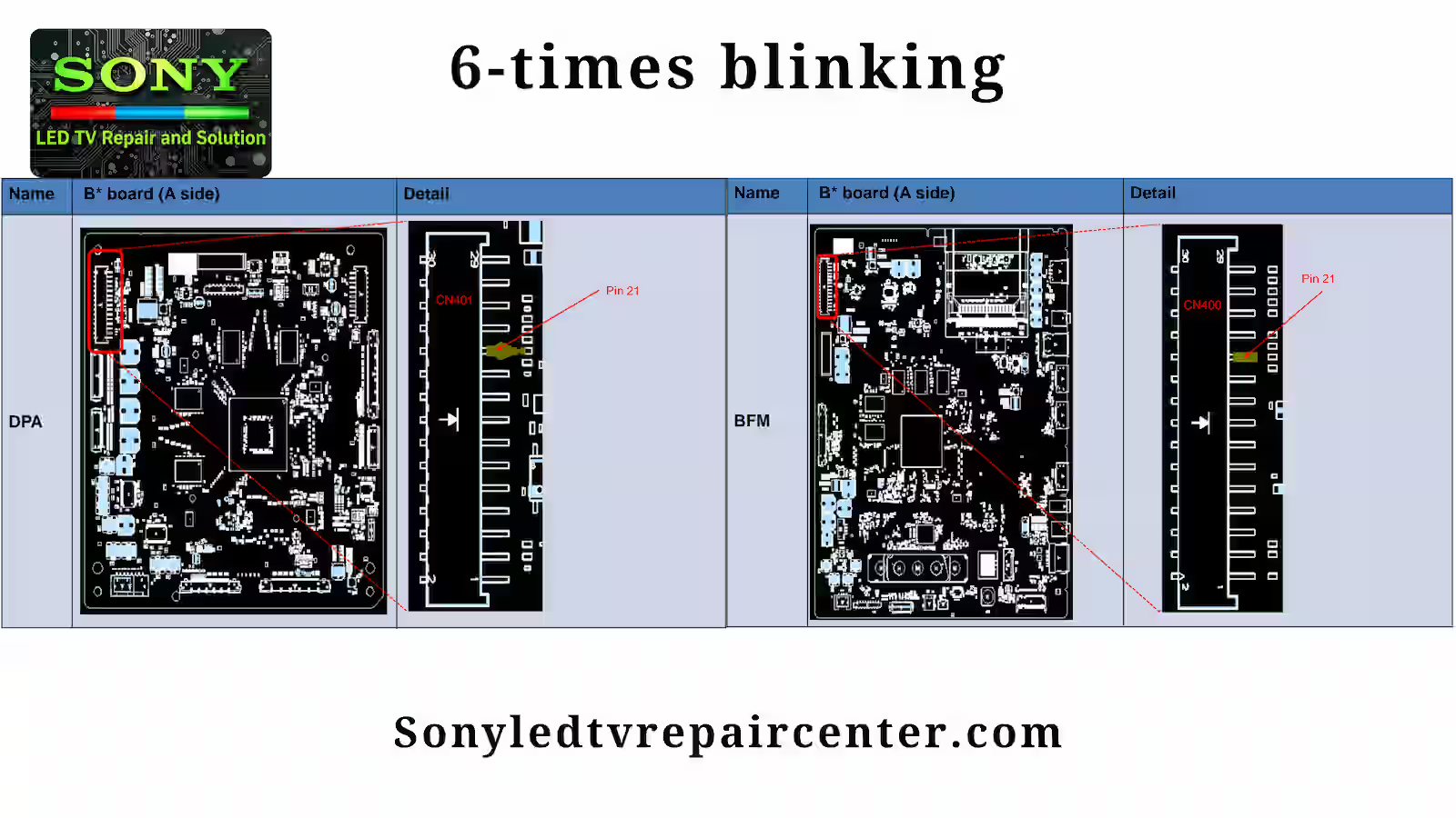
6 Blinks in the Sony KD-49X7D LED TV indicate a backlight protection error related to the BL_ERR_DET detection line. When the standby LED flashes six times, technicians should measure the voltage of BL_ERR_DET at pin 21 of CN400 on the BFM board. This signal confirms whether the backlight system is operating correctly or if a protection condition has been triggered.
If the measured voltage is ≥ 1.9V, the harness and connections between the G/LD board and the B board must be inspected carefully. Loose, damaged, or oxidized connectors can cause intermittent backlight errors. If any issue is found, the harness should be replaced. If the harness is confirmed to be normal and no symptom improvement is observed, the BFM board itself may require replacement.
If the voltage is < 1.9V, the fault may be related to the panel’s LED backlight section. In this case, the panel should be checked and replaced if defective. If panel replacement does not resolve the issue, the LED driver (LD board) or the G board may be responsible and should be replaced accordingly.
This structured diagnostic approach helps accurately isolate backlight-related failures and ensures efficient repair of the six-blink protection condition.
6 – Blink Error Code – BL_ERR_DET Diagnosis
6 Blinks in the Sony KD-49X7D LED TV indicate a backlight protection fault detected through the BL_ERR_DET line. When the standby LED flashes six times, technicians should first measure the voltage of BL_ERR_DET at pin 21 of CN400 on the BFM board. This signal determines whether the backlight error is being triggered by a communication issue or a hardware failure in the LED driving circuit.
If the measured voltage is ≥ 1.9V, the next step is to inspect the harness and connections between the G/LD board and the B board. Any loose, damaged, or poor connection can cause this error condition. If a wiring issue is found, the harness should be replaced. If the harness and connections are confirmed to be normal but there is no symptom improvement, the BFM board may be defective and should be considered for replacement.
If the voltage is < 1.9V, the problem may be related to the panel’s backlight section. In this case, the panel should be checked and replaced if necessary. If replacing the panel does not resolve the issue, the LED driver (LD board) or the G board should be inspected and replaced accordingly.
Following this systematic procedure ensures accurate troubleshooting of the six-blink backlight protection error and prevents unnecessary replacement of major components.
7 – Blink Error Code – Over Temperature
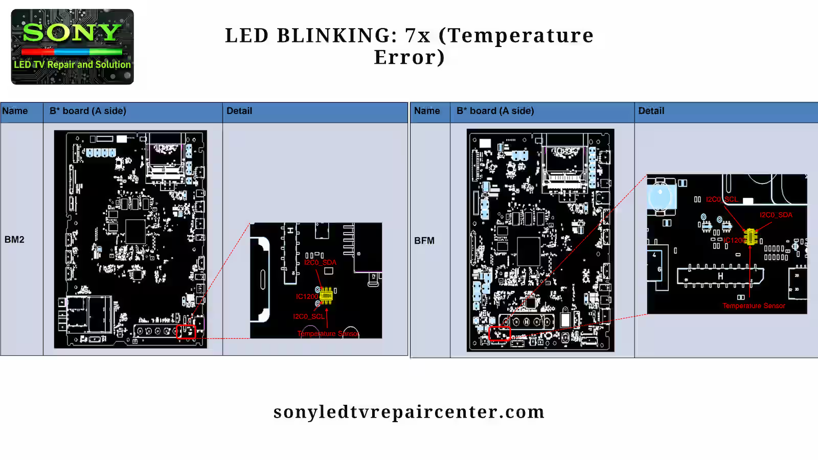
7 Blinks in the Sony KD-49X7D LED TV indicate an over-temperature protection or temperature monitoring circuit fault. When the standby LED flashes seven times, the first step is to evaluate the operating environment. Check whether the installation conditions are appropriate, including room temperature, ventilation, and airflow around the unit. If the TV is placed in a confined or poorly ventilated area, move it to a better-ventilated location and observe whether the symptom improves.
If the environment is confirmed to be normal and the issue persists, inspect the B* Board. If the board is found defective (NG), replace the B* Board and perform an aging test for several hours to confirm stability. If the problem continues, check the I2C_C bus communication related to the temperature sensing circuit. Any abnormal communication, bus short, or data line issue can trigger the seven-blink protection.
If the I2C_C bus is not functioning correctly, inspect the temperature sensor circuit for bus dumping, shorting, or related component failure. If necessary, replace the faulty components or the associated board. This structured diagnostic process ensures accurate identification of overheating or temperature detection faults and restores reliable operation of the television.
Conclusion
In this detailed guide on Sony KD-49X7D Complete Blink Error Code Solution, we have carefully explained each standby LED blinking pattern along with its possible causes, effects, and step-by-step troubleshooting procedure. From power supply checks to panel, T-Con, audio, backlight, and temperature-related diagnostics, every blink code has been covered to help technicians accurately isolate faults and avoid unnecessary board replacement.
By following this structured diagnostic approach, repair professionals can confidently identify the root cause of the problem and restore proper functionality to the Sony KD-49X7D LED TV. Understanding these blink error codes not only saves time but also improves repair accuracy and overall service efficiency.
Sony XR vs Other TV Processors
KLV-46R452A Complete Red Light Blinking Guide

Shaukat Ali has over 30 years of experience in LED TV repair, specializing in chip-level repair work. He is an expert in Sony LED TVs, and also repairs other major brands like Samsung, TCL, Orient, and Haier. His expertise includes display panel faults, motherboard issues, power supply circuits, T-Con, and HDMI faults. Based in Lahore, he shares real-time fault finding cases from daily repair work to help technicians and learners with practical experience.
📞 Contact: +92 321 4066054